
The choice of communication protocol between the PLC controller and the peripheral device most often depends on the main device, i.e. usually the PLC controller. Of course, it is not always possible, then various types of converters come into play, but this is a separate topic.
In other words, we choose what we know and like, but it is not always the most optimal choice. Occasionally, certain devices offer slightly more functionality with certain network protocols. In this article, I would like to present an example of communication configuration via EtherNet / IP between a PLC and a FANUC robot. In the first part, I will present the method of establishing communication step by step. In the second part, I would like to discuss some non-obvious features related to the EtherNet / IP option in FANUC robots that give you an advantage over other methods.
STEP1 – I / O MAP
Before starting the robot-PLC communication setup, it is worth preparing a list of signals that we want to send between devices. FANUC has some predefined groups of signals that are worth, and some should be included in such a list.
The most important of these groups is UOP – User Operator Panel, here are the signals necessary for the cooperation of the robot with the PLC. With their help, we can run the robot program using the PLC controller. Cell Interface and SOP (Standard Operator Panel) groups contain a set of useful signals for integrators. Similarly, Interconnect where we can, for example, “pass” the status of internal safety signals to the controller (For monitoring purposes only).
As a rule, for a given process, the most important groups will be 3 – Digital (digital inputs / outputs) and 5 – Group (digital inputs / outputs grouped in packages). It is here that we assign signals controlling the course of a given process (process variables).
An example signal map may look like this:
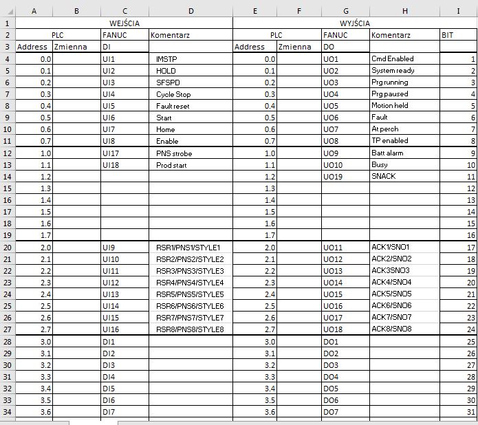
As you can see, at the beginning I put the UOP signals which are 3 bytes long. Then I put digital inputs and outputs. As a rule, between them I also put I / O used as standard in each application (cell interface), signals monitoring the robot status, etc. For demonstration purposes, however, it is not necessary, so I present here a simplified version.
From the PLC side, the number of inputs / outputs can be set practically freely, we are limited only by the size of the Ethernet / IP frame (about 1400 bytes) and the number of adapters (slaves) working with a given scanner (master). The frame is divided into all slave devices, so if we have more devices on ENIP, this should be taken into account when planning. By default, a certain number of I / O, registers and positional registers are set in the robot. However, there is nothing to prevent these values from being changed as needed. To do this, enter the MAINTENANCE mode using the Controlled Start function.
STEP2 – Connection
From the controller side, the network connection settings obviously depend on the type used. There is an AOP (add-on-profile) ready for AB controllers. I, on the other hand, use B&R controllers which, despite the need to buy an EtherNet / IP communication module, also allow very easy and quick integration.
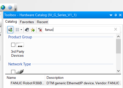
We add the Fanuc robot EDS file to Automation Studio:
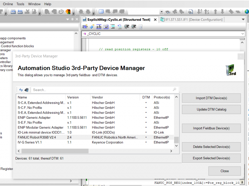
After adding the EDS file, add the robot to the device list:
We set the scanner’s IP address (master):
Frame size – in my case 64 bits in both directions:
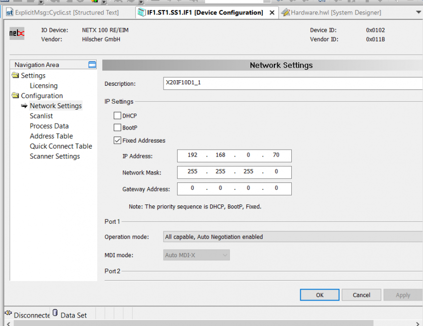
From the robot’s side, we go to the network settings on the teach pendant, where we set the robot’s IP address:
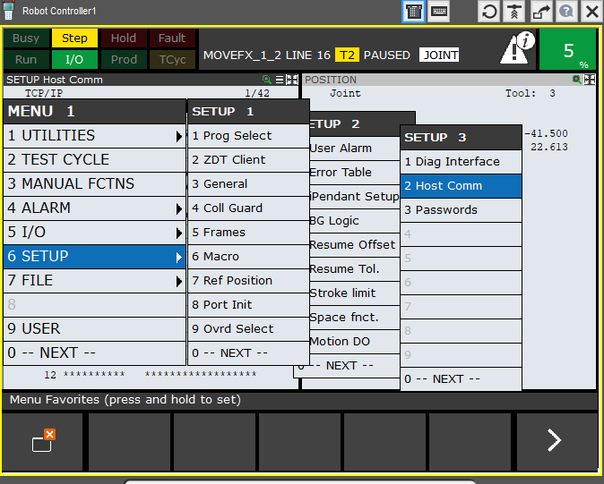
SETUP> SETUP2> Host Comm> TCP / IP
We ping and check if both devices are visible in the network.
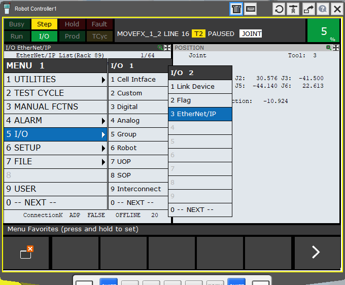
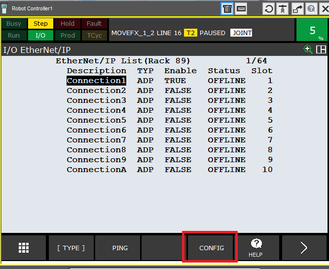
Then go to the Ethernet IP settings. MENU> I / O>> Ethernet / IP
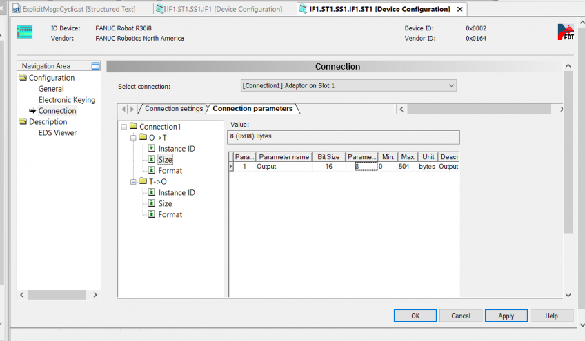
We choose the available connection that we want to use (we can have more than one ENIP adapter in the robot controller), then select F4 – Config
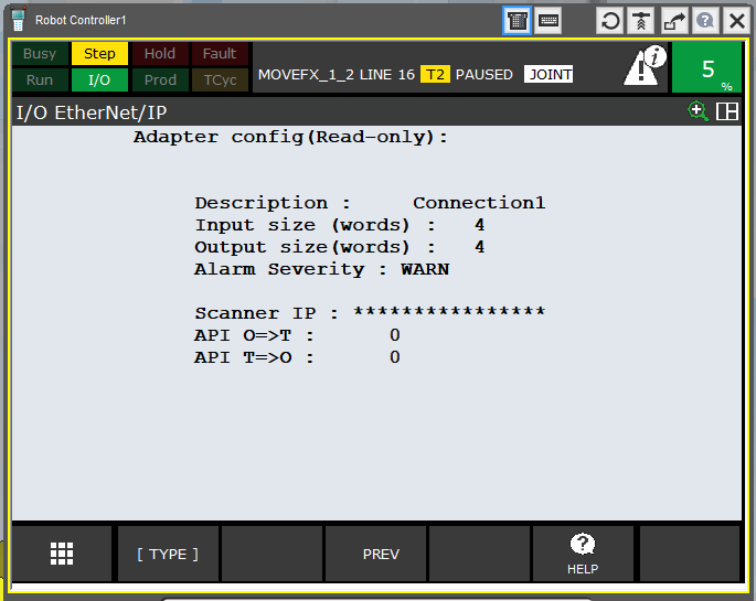
In the configuration window, we set the amount of data transferred, remember that the values are given as words, i.e. groups of 16 bits. So 4 words / 8 bytes / 64 bits, that is as set in the PLC.
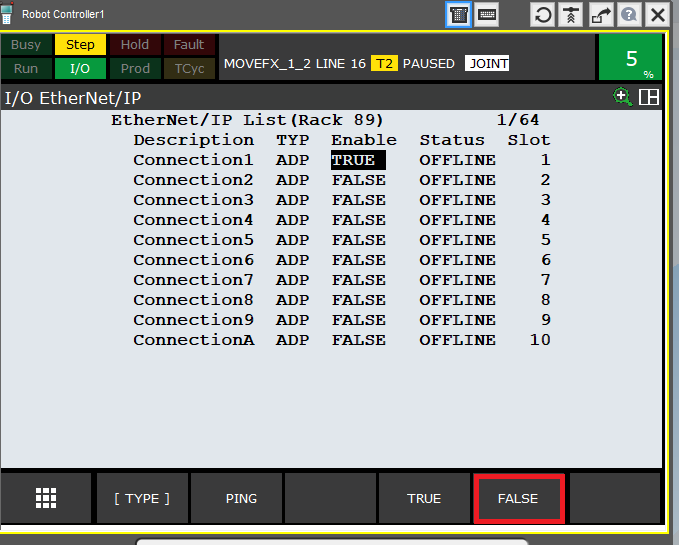
If we want to change the number of words, first we have to deactivate the connection on the previous screen.
Change the configuration:
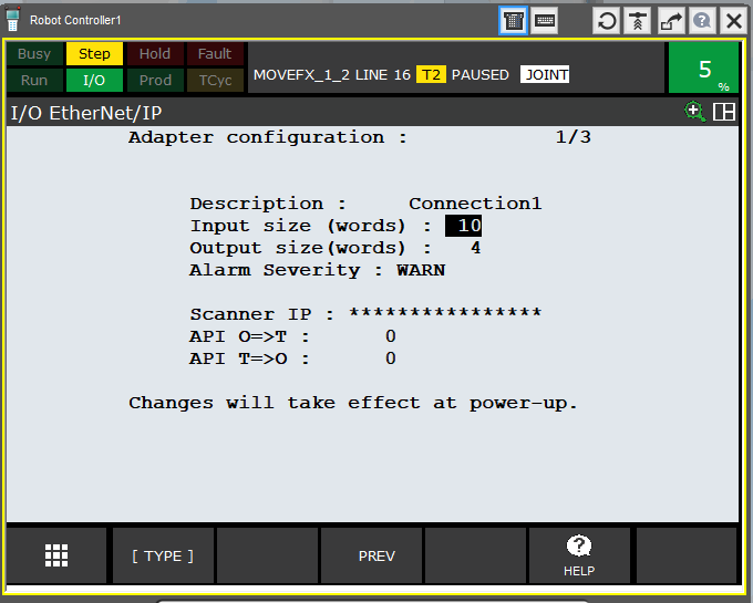
Activate and restart the robot controller.
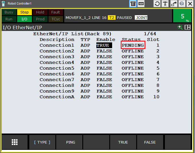
If everything is set correctly on the PLC side, after restarting the controller, we should see the status change OFFLINE -> RUNNING. I was using ROBOGUIDE offline when writing the article, so the connection is inactive.
Ok, this is how we established the connection between the controller and the robot. Unfortunately, this does not yet lead to an exchange of process data.
STEP3 – I / O configuration
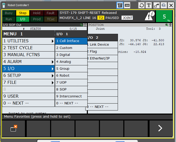
To do this, go to MENU> I / O> Digital
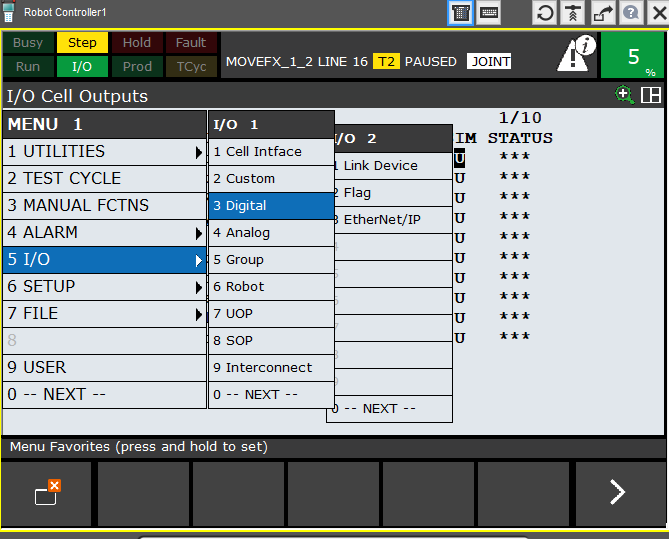
After clicking ENTER, you should see a screen similar to the following:
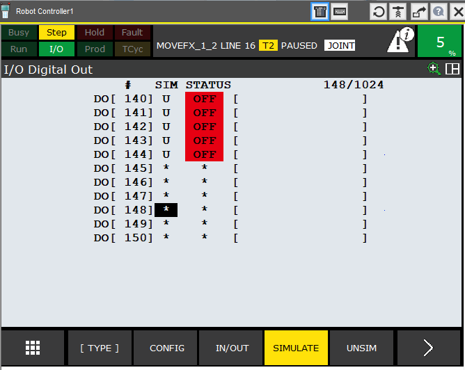
Some inputs may already be assigned, while uninitialized (inactive) inputs / outputs will be marked with an asterisk *.
Press F2 (Config) and go to the configuration screen. This is where our inputs / outputs will be assigned to the appropriate places, i.e. in the case of FANUC – racks and slots.
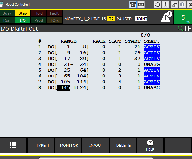
EtherNe / IP is rack 89, we have only one robot arm plugged into the controller, so one adapter – slot 1.
Enter the range of inputs that interest us, which we want to use, assign them to the appropriate rack and slot, give the start bit, i.e. where in the communication frame the given group of inputs / outputs will be located. To determine the start bit, we refer to the prepared table and read where the given I / O group is to be mapped.
In the example below, for inputs 1-40 it will be bit 25
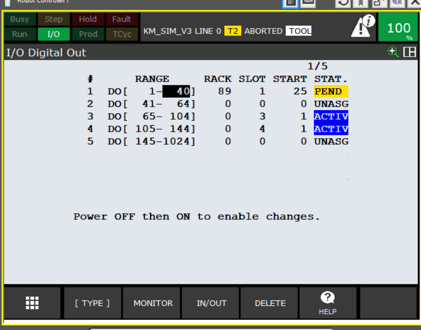
As you can see after making changes, the STATUS of the edited inputs / outputs has changed to PENDING. For the changes to take effect, restart the robot controller or select Cycle Power with FCTN.
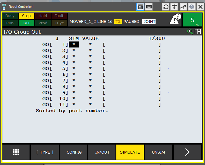
We configure group outputs depending on the needs, if we want to send values other than the bool type. We can group 2 to 16 lines that may overlap with digital I / O.
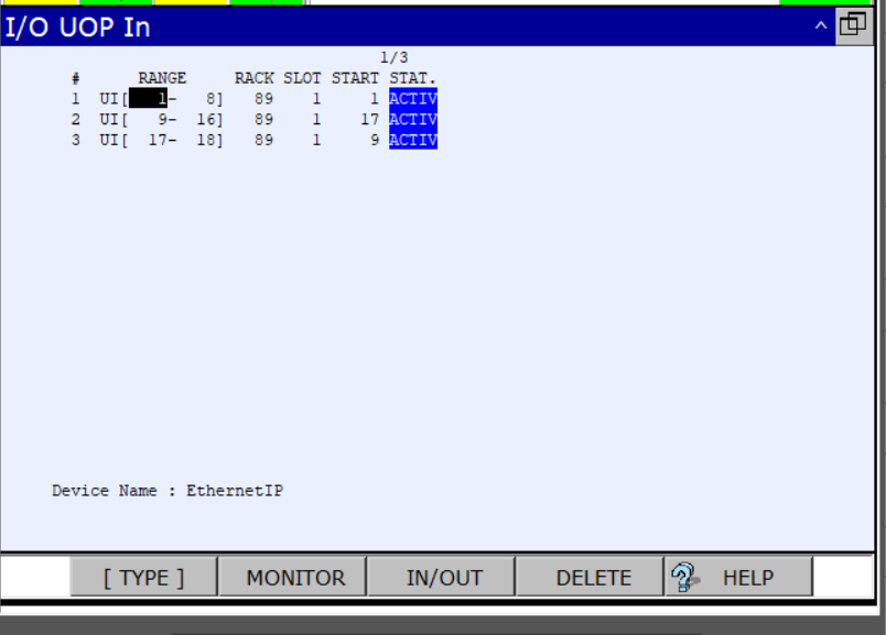
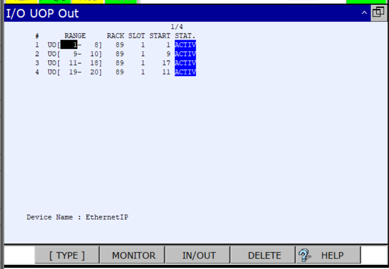
We do the same in the case of UOP signals:
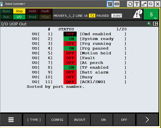
Since in step 1 I determined that the UOP signals will occupy the first three bytes, I set the configuration as follows:
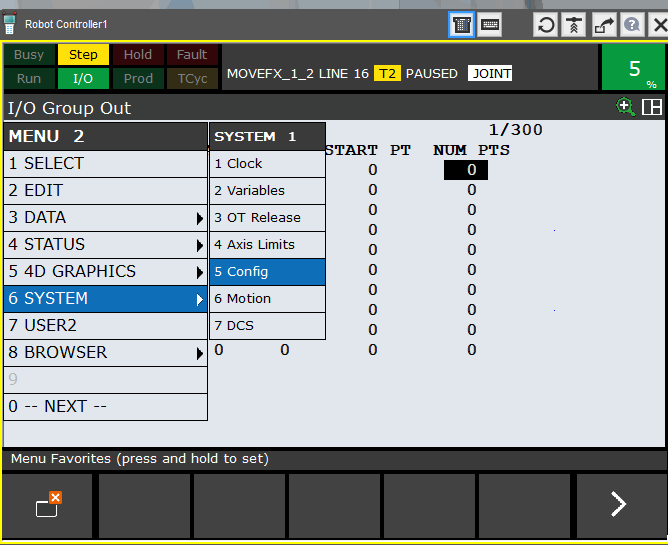
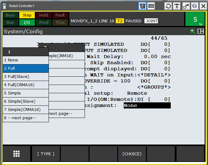
Moreover, to enable the exchange of UOP signals between the robot controller and the controllers, this option must be activated in the controller. To do this, go to the system configuration menu on the Teach Pendant
We find position number 7 – Enable UI Signals
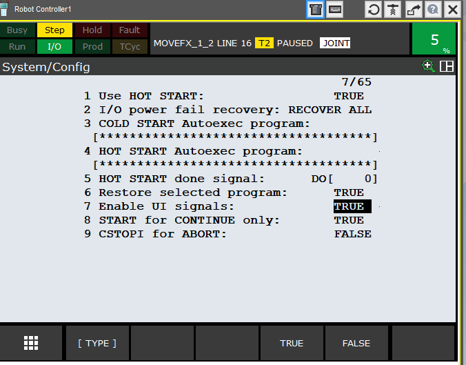
If the value is set to FALSE, the external signals (UI [1 to 18]) are disabled. Set this value to TRUE to allow programs to be started with the PLC. In addition, you need to make sure how the UOP signals are assigned. In the same menu we find position 44:
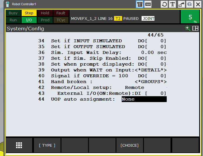
We choose the signal allocation method (FULL).
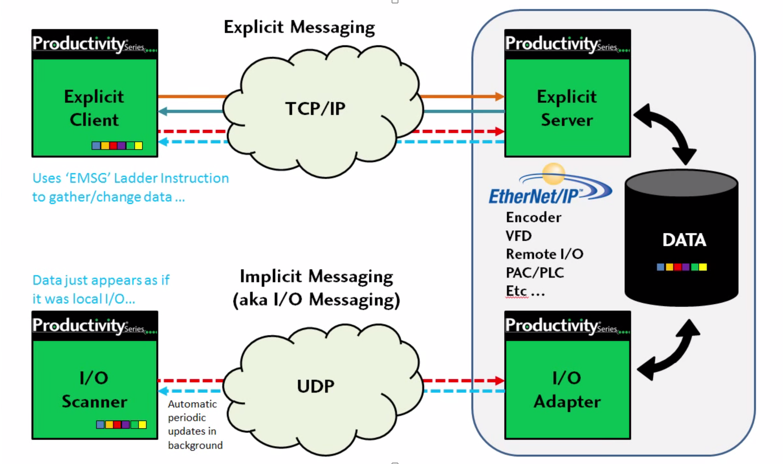
EtherNet / IP – CIP explicit messaging
In addition to the implicit communication method described above using the connectionless UDP transmission protocol, there is also the so-called explicit using the connection-oriented TCP protocol. The first of these, as described above, is for “real-time” data transfer. The second, on the other hand, is used for acyclical sending of messages – data packets, between the client and server:
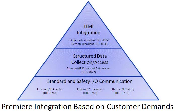
This is where the advantage of this type of communication method over other FANUC robots comes in. Probably due to the popularity of both FANUC robots and the EtherNet IP standard in the USA, FANUC has quite significantly expanded the functions available through this communication method:
With this method, we can transfer large amounts of data very easily and quickly. Appropriate use of ready-made function blocks available in the PLC device allows access to whole groups of registers, including position registers. We can also access error codes or alarm contents displayed on the teach pendant.
This opens up far-reaching possibilities for integrating FANUC robots into any PLC equipped with EtherNet IP. Thanks to this, from the HMI level, we can change, for example, the tool offset or make User Frame corrections without clogging the I / O connection. We don’t have to use dozens of digital inputs to send a set of numbers. It is enough to send what we need and when we need it with one FB.
Practical example
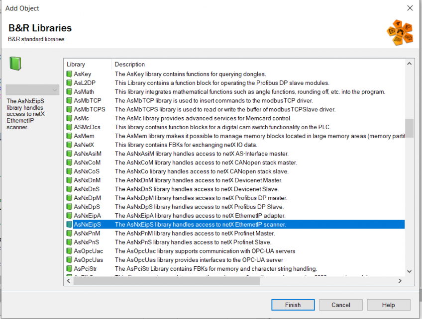
I will present the application of this type of data exchange on the example of a B&R controller. To be able to use these functions, the AsNxEipS library available in the group of standard B&R libraries should be added to the project.
Then we can create a subroutine to handle explicit messages. To establish a connection, we need to provide the necessary attributes for the function. A detailed description of the use of the function can be found in the Automation Studio help, while the parameters of the message we want to send can be found in the Fanuc company’s manual provided when buying a robot with the EtherNet IP option.
In order to send a message, I will use the eipsObjUnconnectedMessage function:
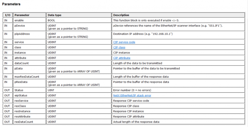
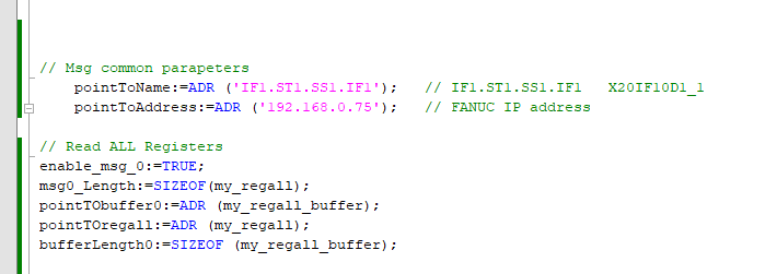
The common arguments of the eipsObjUnconnectedMessage function are the hardware address of the scanner and the IP address of the adapter.
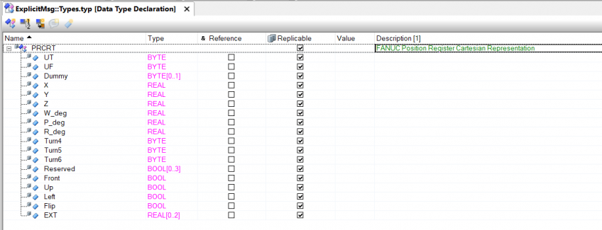
It remains to create appropriate data structures that can accept the transmitted information (details also in the FANUC manual)
The example below shows an example of a request to read 10 positional registers – from 101 to 110.
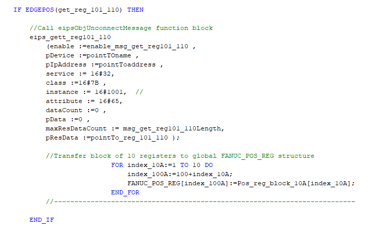
The following parameters can be read from the instruction:
service 16 # 32- Gett_Attribute_Block
class 16 # 7B – services for positional registers
attribute 16 # 65 (dec 101) – number of the first register
instance 16 # 1001- ten registers in group 1 (See table below)
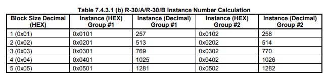
As shown in the table above, the value of the instance number should be calculated according to the presented rule. In the case of other services, e.g. for a single register, the instance number is given directly in the instruction. The next arguments of the eipsObjUnconnectedMessage function are indicators of the size of the transmitted information and its location.
It remains to verify the correctness of the sent message. To do this, send a request from the controller and check whether the data on both sides is correct. If this is not the case, the error information (number) will be issued to the resDataCount output. This should allow you to successfully diagnose the correctness of the function call.
SUMMARY
Both the connection setup method presented in the first three paragraphs and the EtherNet / IP messaging method are universal. As I mentioned, the first one is almost independent of the type of protocol – only the rack numbers will be different. The second, however, concerns all devices using EtherNet / IP, in which the manufacturer has provided such services. So let’s read the instructions carefully, very often we can access various functions of the device in this way. So I hope you will find this information useful. Good luck!
Author: Krzysztof
fantastic points altogether, you simply won a new reader. What would you recommend about your submit that you just made some days in the past? Any certain?