In the wiring diagrams we can find symbols for contact control devices. The part that causes the contact to be engaged or switched is called the actuator, which basically can be any displacement phenomenon, for example: push, twist, zoom, rotate, light reflection, sound reflection, etc.
The structure of a contact switching device symbol consists of at least three parts: actuator, actuator function and contact, to this must be added descriptions that appear around the symbol for example device ID, description, contact connection numbers. Below is an example of a pushbutton (manual override) without self-return that activates a normally open NO contact:
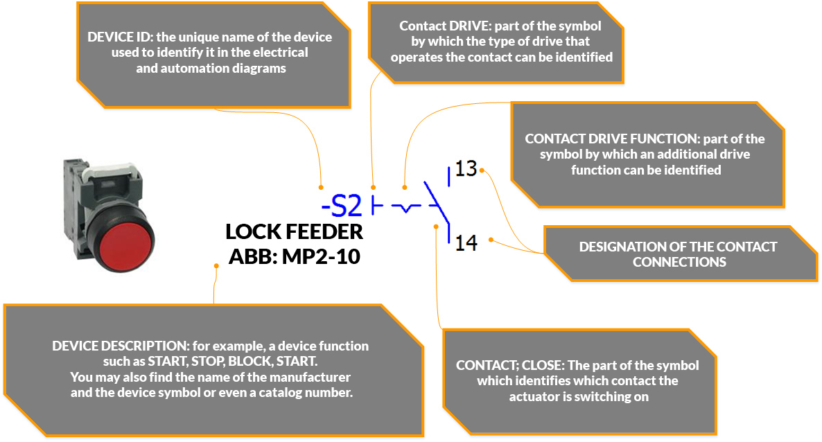
What’s the issue with NO and NC contacts? Read more here:
More about switches and contact drives; electrical symbols:
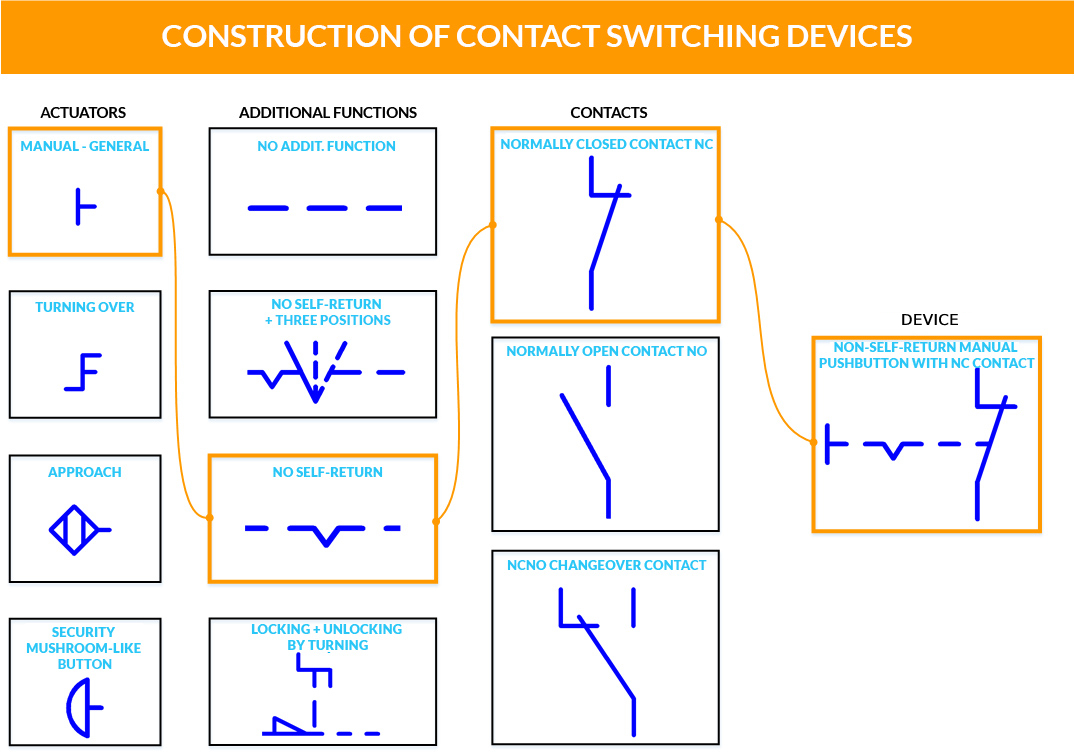
Electrical symbols for a contact switching device consist of at least 3 parts, although some cases may be more elaborate. Below, for comparison, I show some possible options (a few of many) for building a contact switching device with an additional function.
Electrical Symbols – MULTIPOSITION SWITCHES
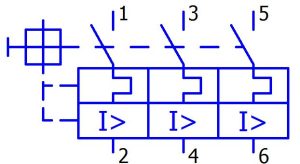
The multi-position switches in the diagrams take different forms, but the analysis of each is very similar. Let’s take a look at a three-position switch with two normally open (NO) contacts:
This switch has two contact fields. In a wiring diagram, the contacts of such a switch are usually on one side and connected by a dashed line. It happens, however, that one contact field can be on page A and the other contact field on page B – in this case the symbols have page references (page.column) linking the symbol to a logical whole.
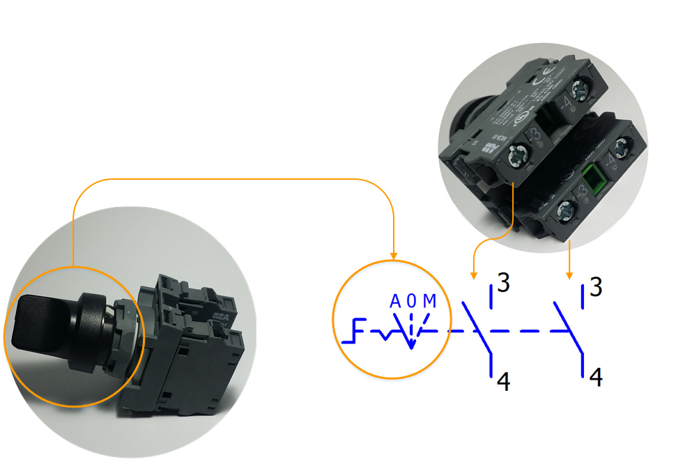
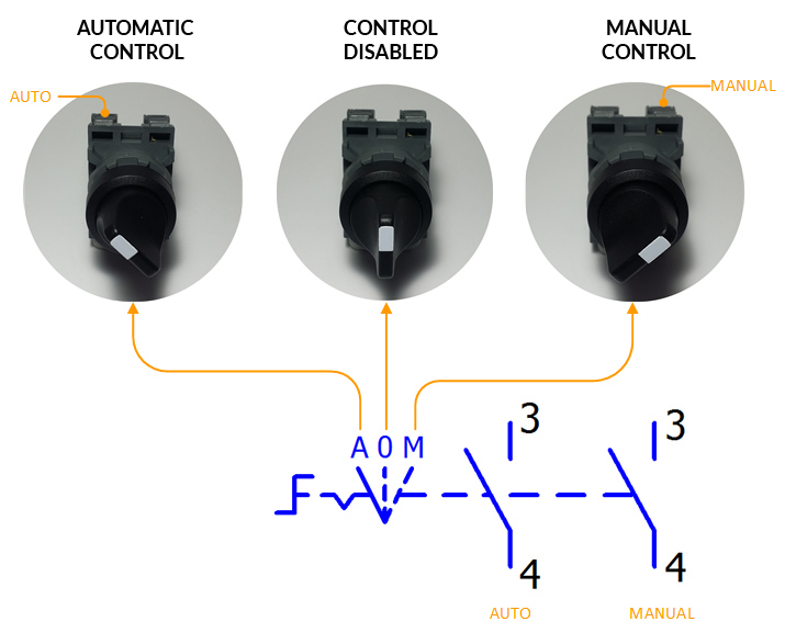
Multi-position switch symbols typically show the number of positions as slanted dashes along with an abbreviated description of each position (e.g., A-0-M). Below is an example of a three-position switch:
- Left position – automatic control, left contact closed,
- Middle position – control disabled, both contacts are off (opened),
- Right position – manual control, right contact closed.
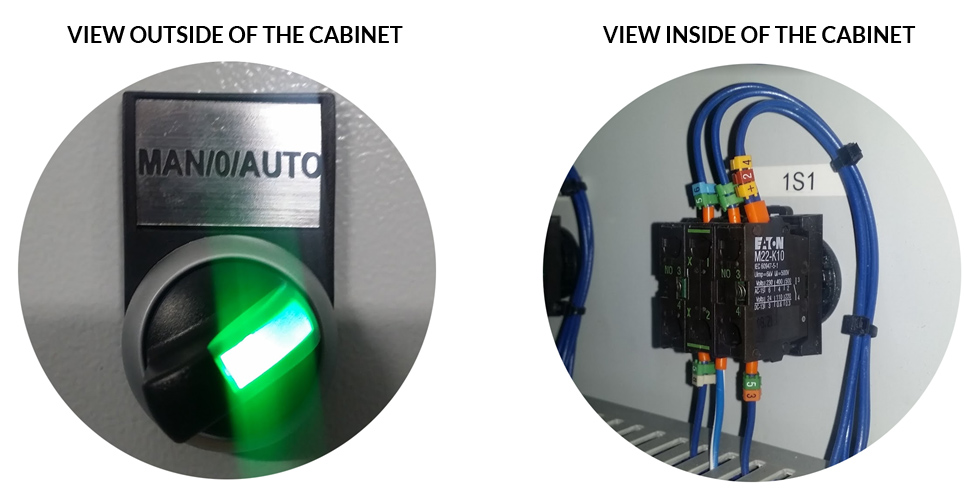
An example of another three-position switch with an indicator LED in an electrical cabinet:
ELECTRICAL AND AUTOMATIC SYMBOLS – CONTACT DRIVERS:
Manual drive – generic symbol
NAME: Manual drive with normally open NO contact, general symbol.
SOURCE: Standard: PE-EN 60617, position (point): 2-13-01
ELECTRICAL SYMBOL DESCRIPTION:
DRIVE: Generic symbol for manual actuators. It can represent any manually operated actuator such as a button, switch, lever, etc.
SPECIAL FUNCTION: not specified (no special character on dashed line)
CONTACT: Normally open NO contact. Actuating the manual drive will short (close) the NO contact
OTHER: Although this is a generic symbol for all manual drives, it is good practice to use specific symbols for each drive type.
SAMPLE VIEW
Manual drive NC – generic symbol
NAME: Manual drive with normally closed NC contact, generic symbol.
SOURCE: Standard: PE-EN 60617, position (point): 2-13-01
ELECTRICAL SYMBOL DESCRIPTION:
DRIVE: Generic symbol for manual actuators. It can represent any manually operated actuator such as a button, switch, lever, etc.
SPECIAL FUNCTION: not specified (no special character on dashed line)
CONTACT: Normally closed NC contact. Actuating the manual drive will disconnect (open) the NC contact
OTHER: Although this is a generic symbol for all manual drives, it is good practice to use specific symbols for each drive type.
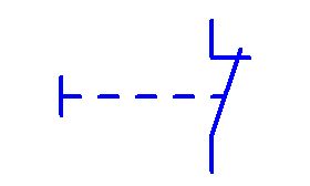
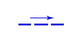
Manual drive, NO contact, without automatic return
NAME: Manual drive with normally open NO contact without automatic return, generic symbol.
SOURCE: Standard: PE-EN 60617, position: 2-13-01 and 2-12-08
ELECTRICAL SYMBOL DESCRIPTION:
DRIVE: Generic symbol for manual actuators. It can represent any manually operated actuator such as a button, switch, lever, etc.
SPECIAL FUNCTION: Generic symbol for manual actuators with specified hold function (no automatic return). The hold function means that a change of position of such an actuator, e.g. pressing down, turning, will maintain this state until it is pressed or turned again.
CONTACT: Normally open NO contact. activation of manual actuator causes closing of NO contact
OTHER: although this is a generic symbol for all manual drives, it is good practice to use specific symbols for each drive type.
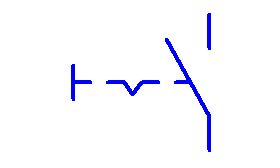
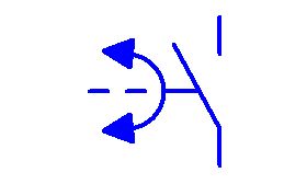
Manual drive NO with change-over contact
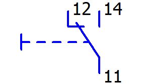
NAME: Manual actuator with switch contact from 11,12 to 11,14, generic symbol.
SOURCE: Standard: PE-EN 60617, position (point): 2-13-01
ELECTRICAL SYMBOL DESCRIPTION:
DRIVE: Generic symbol for manual actuators. It can represent any manually operated actuator such as a button, switch, lever, etc.
SPECIAL FUNCTION: Generic symbol for manual actuators with specified hold function (no automatic return). The hold function means that a change of position of such an actuator, e.g. pressing down, turning, will maintain this state until it is pressed or turned again.
CONTACT: change-over contact. Activation of the manual actuator switches the contact from terminals 11,12 (NC) to 11,14 (NO)
OTHER: Although this is a generic symbol for all manual drives, it is good practice to use specific symbols for each drive type.
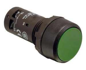
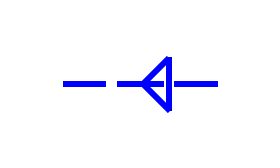
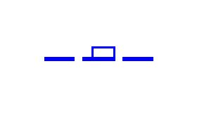
Push-on actuator
NAME: Manual push-on actuator with normally open NO contact, generic symbol.
SOURCE: Standard: PE-EN 60617, position (point): 2-13-05
ELECTRICAL SYMBOL DESCRIPTION:
DRIVE: Push-on actuator
SPECIAL FUNCTION: not specified (no special character on dashed line)
CONTACT: Normally open NO contact. when pressed, the NO contact closes.
OTHER: …
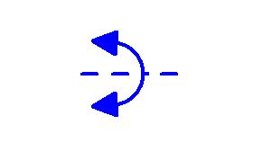
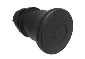
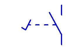
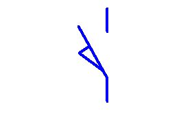
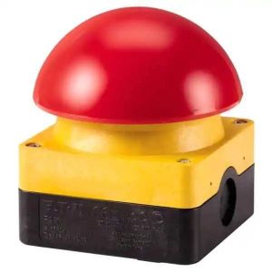
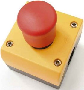
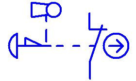
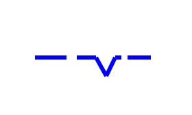
Pull-back manual actuator
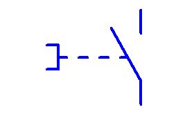
NAME: Pull-back manual actuator with normally open NO contact, generic symbol.
SOURCE: Standard: PE-EN 60617, position (point): 2-13-02
ELECTRICAL SYMBOL DESCRIPTION:
DRIVE: Pull-back manual actuator
SPECIAL FUNCTION: not specified (no special character on dashed line)
CONTACT: Normally open NO contact. pulling down will close NO contact
OTHER: this symbol is mainly used for mushroom-shaped switches
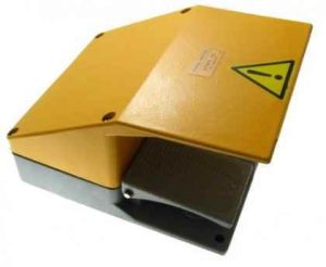
Foot pedal drive
NAME: Foot drive; pedal with NO (normally open) contact, generic symbol.
SOURCE: Standard: PE-EN 60617, position (point): 2-13-10
ELECTRICAL SYMBOL DESCRIPTION:
DRIVE: Foot operated, pedal
SPECIAL FUNCTION: not specified (no special character on dashed line)
CONTACT: Normally open NO contact. Depressing the pedal will close the NO contact
OTHER:
SAMPLE APPEARANCE:
Manual turn-over actuator
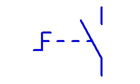
NAME: Manual turn-over actuator with normally open NO contact; toggle switch; switch symbol.
SOURCE: Standard: PE-EN 60617, position (point): 2-13-04
ELECTRICAL SYMBOL DESCRIPTION:
DRIVE: manual by turn over
SPECIAL FUNCTION: not specified (no special character on dashed line)
CONTACT: Normally open NO contact. Turning will close the NO contact
OTHER: …
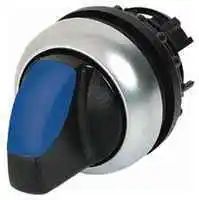
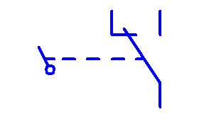
Manual turn-over actuator without self-return
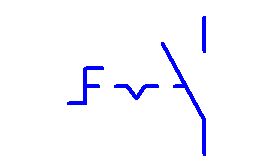
NAME: Manual turn-over actuator with normally open NO contact; without self-return, switch; switch symbol.
SOURCE: Standard: PE-EN 60617, position: 2-13-04 and 2-12-08
ELECTRICAL SYMBOL DESCRIPTION:
DRIVE: manual by turn-over
SPECIAL FUNCTION: The special function “sustain” is specified in this symbol (placed on the dashed line). Sustained function (no self-return) means that if the position of such an actuator is changed by turning, it will remain in that state after turning until it is turned again
CONTACT: Normally open NO contact. Turning will close the NO contact
OTHER: …
SAMPLE APPEARANCE:
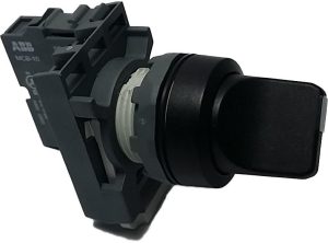
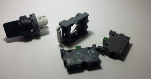
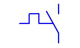
Two-position switch with description
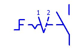
NAME: Two-position rotary manual operator with three NO (normally open) contact fields without self-return; swich; two-position two-position switch
SOURCE: standard: PE-EN 60617, position: 2-13-04 and 2-12-08
ELECTRICAL SYMBOL DESCRIPTION:
DRIVE: manual by turn-over
SPECIAL FUNCTION: The symbol specifies two special functions: “sustain” and “two switch positions with description” (placed on the dashed line). Sustained function (no self-return) means that if the position of such an actuator is changed by turning, it will remain in that state after turning until it is turned again The two position function of the switch means that the switch can be turned (set) to two different positions, labeled as 1 and 2.
CONTACT: Normally open NO contact. Turning from position 1 to 2 will close the NO contact
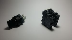
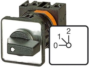
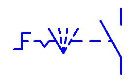
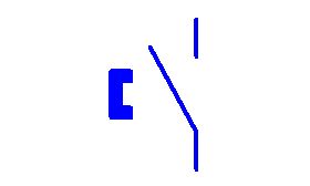
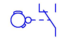
Three-position (three-way) switch
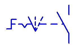
NAME: Three-position turning-over manual operator with a NO (normally open) contact without self-return; swich; three-position three-way switch
SOURCE: standard: PE-EN 60617, position: 2-13-04 and 2-12-08
ELECTRICAL SYMBOL DESCRIPTION:
DRIVE: manual by turn-over
SPECIAL FUNCTION: The symbol specifies two special functions: “sustain” and “three switch positions with description” (placed on the dashed line). Sustained function (no self-return) means that if the position of such an actuator is changed by turning, it will remain in that state after turning until it is turned again The three position function of the switch means that the switch can be turned (set) to three different positions for example: left, center and right position.
CONTACT: Normally open NO contact. Turning will close the NO contact
OTHER: … Such a symbol usually has at least as many contacts as the positions to be switched. If such a symbol is drawn with one contact it may mean that the other contacts are on other pages of the wiring diagram.
SAMPLE APPEARANCE:
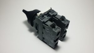
Four-position switch
Similar to three-position switch
Switch with three contact fields
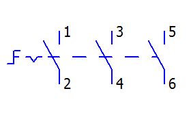
NAME: Two-position turning-over manual operator with three NO (normally open) contact fields without self-return; switch; two-position switch, master circuit breaker
SOURCE: standard PE-EN 60617, position: 2-13-04 and 2-12-08
ELECTRICAL SYMBOL DESCRIPTION:
DRIVE: manual by turn-over
SPECIAL FUNCTION: The special function “sustain” is specified in this symbol (placed on the dashed line). Sustained function (no self-return) means that if the position of such an actuator is changed by turning, it will remain in that state after turning until it is turned again
CONTACT: three normally open NO contact fields. Turning will switch on three contacts at once.
OTHER: Typically, this symbol is used for main circuit breakers (power switch).
SAMPLE APPEARANCE:
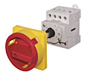
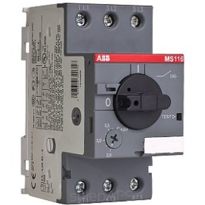
Thermally actuated drive
NAME: Thermal actuation; thermal release
SOURCE: standard: PE-EN 60617, position (point): 2-08-01
ELECTRICAL SYMBOL DESCRIPTION:
DRIVE: thermal actuator; thermal; thermal trip; thermic
SPECIAL FUNCTION: thermal triggering. Typically, exceeding the temperature in the wire triggers a contact switch.
CONTACT: exceeding the temperature in the circuit will short the normally open NO contact
OTHER: The most common application for this drive is in motor protection – motor circuit breaker; thermic
SAMPLE APPEARANCE:
Motor protection switch
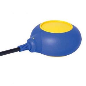
Float switch
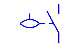
NAME: Float drive; float switch; level switch; float;
SOURCE: standard: PE-EN 60617, position (point): 2-14-01
ELECTRICAL SYMBOL DESCRIPTION:
DRIVE: float actuator; float
SPECIAL FUNCTION: none
CONTACT: When the liquid level raises the float, the normally open NO contact is closed
OTHER: Floats are used to confirm that some level has been reached. For example, it can be the level of switching on or off of some device (pump) or the detection of a high or low level.
SAMPLE APPEARANCE:
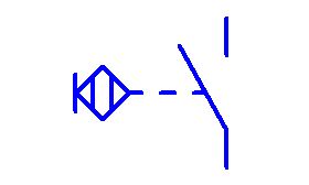
Magnetic switch
NAME: Drive by magnet approach
SOURCE: EPLAN
ELECTRICAL SYMBOL DESCRIPTION:
DRIVE: magnet
SPECIAL FUNCTION: none
CONTACT: Bringing the magnet close to the contact closes the normally open NO contact
OTHER: a type of contact switching rarely used in automation.
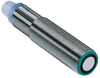
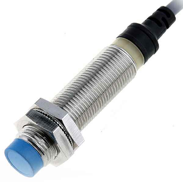
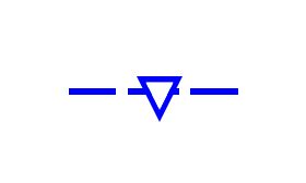
Proximity switch – general symbol
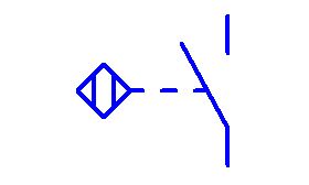
NAME: Proximity actuator – general symbol for proximity actuators
SOURCE: standard: PE-EN 60617, position (point): 2-13-06
ELECTRICAL SYMBOL DESCRIPTION:
DRIVE: proximity actuator, proximity drive
SPECIAL FUNCTION: none
CONTACT: bringing a body that the sensor responds to close to it causes a normally open NO contact to close
OTHER: as proximity drives we can consider: optical, acoustic, inductive, magnetic sensors.
SAMPLE APPEARANCE:
Touch switch
NAME: Tap drive
SOURCE: standard: PE-EN 60617, position (point): 2-13-07
ELECTRICAL SYMBOL DESCRIPTION:
DRIVE: touch drive
SPECIAL FUNCTION: none
CONTACT: touching the sensor results in closing the normally open NO contact
OTHER: for example, capacitive sensors (reacts to touch)
Magnetic switch
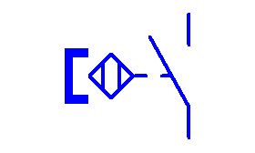
NAME: Magnetic reed switch drive
SOURCE: standard: PE-EN 60617, position (point): 2-13-06
ELECTRICAL SYMBOL DESCRIPTION:
DRIVE: magnetic actuator
SPECIAL FUNCTION: none
CONTACT: magnet approaching the sensor causes the normally open NO contact to close
OTHER: other name: reed switch
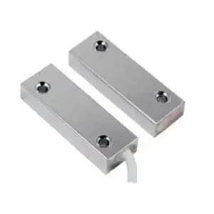
SAMPLE APPEARANCE:
Magnetic sensor; reed switch:
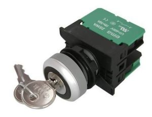
Key-operated drive
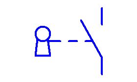
NAME: Key-operated drive; key-operated switch
SOURCE: standard: PE-EN 60617, position (point): 2-13-13
ELECTRICAL SYMBOL DESCRIPTION:
DRIVE: key-operated drive
SPECIAL FUNCTION: none
CONTACT: turning-over the key causes the normally open NO contact to close
OTHER:
SAMPLE APPEARANCE:
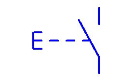
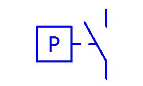
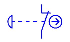
Energy or phenomenon driven

NAME: Energy driven, phenomenon driven
SOURCE: standard: PE-EN 60617, position (point): 2-13-20
ELECTRICAL SYMBOL DESCRIPTION:
DRIVE: an actuator activated by energy, a phenomenon. For example, pressure, current, flow, level, temperature, push, etc.
SPECIAL FUNCTION: none
CONTACT: exceeding the set threshold of energy measurement results in shorting the normally open NO contact
OTHER: The drive energy symbol is placed in the center of the square, e.g. P – pressure.
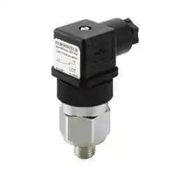
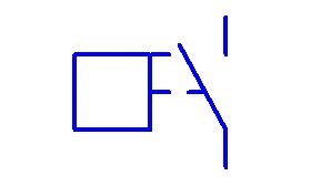
Pressure switch
NAME: Pressure actuator; pressure switch;
SOURCE: standard: PE-EN 60617, position (point): 2-13-20
ELECTRICAL SYMBOL DESCRIPTION:
DRIVE: actuator activated by pressure (or pressure difference).
SPECIAL FUNCTION: none
CONTACT: exceeding the set threshold of preassure results in shorting the normally open NO contact
OTHER:
SAMPLE APPEARANCE:
Flow switch
NAME: Liquid-flow activated drive; flow switch
SOURCE: standard: PE-EN 60617, position (point): 2-13-03
ELECTRICAL SYMBOL DESCRIPTION:
DRIVE: flow-actuated drive.
SPECIAL FUNCTION: none
CONTACT: exceeding the set threshold of flow results in shorting the normally open NO contact
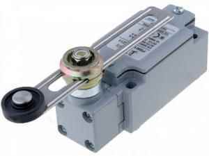
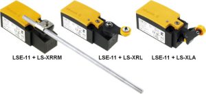
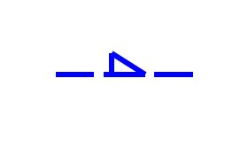
Drive – roller
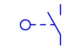
NAME: Roller drive; Roller limit switch
SOURCE: standard: PE-EN 60617, position (point): 2-13-15
ELECTRICAL SYMBOL DESCRIPTION:
DRIVE: roll-operated drive
SPECIAL FUNCTION: none
CONTACT: activation (bending) of the roller results in shorting the NO normally open contact
OTHER:
SAMPLE APPEARANCE:
Drive – cam
NAME: Cam-operated drive with NO contact
SOURCE: standard: PE-EN 60617, position (point): 2-13-16
ELECTRICAL SYMBOL DESCRIPTION:
DRIVE: cam operated drive
SPECIAL FUNCTION: none
CONTACT: The cam can be a disc of various shapes, usually oval. As the cam rotates, the appropriate contacts are engaged depending on the shape of the cam plate.
Cam + roller
NAME: Cam and roller actuator with changeover contact
SOURCE: standard: PE-EN 60617, position (point): 2-13-17
ELECTRICAL SYMBOL DESCRIPTION:
DRIVE: cam and roller operated drive
SPECIAL FUNCTION: none
CONTACT: The cam can be a disc of various shapes, usually oval. As the cam rotates, the corresponding areas of the cam plate press against the roller, which switches the contact from NC to NO. .
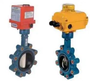
OTHER: Such drives can be found, for example, in throttles where the rotation of the throttle turns the cam. End positions of open and closed press the roller and the contact switches.
SAMPLE APPEARANCE:
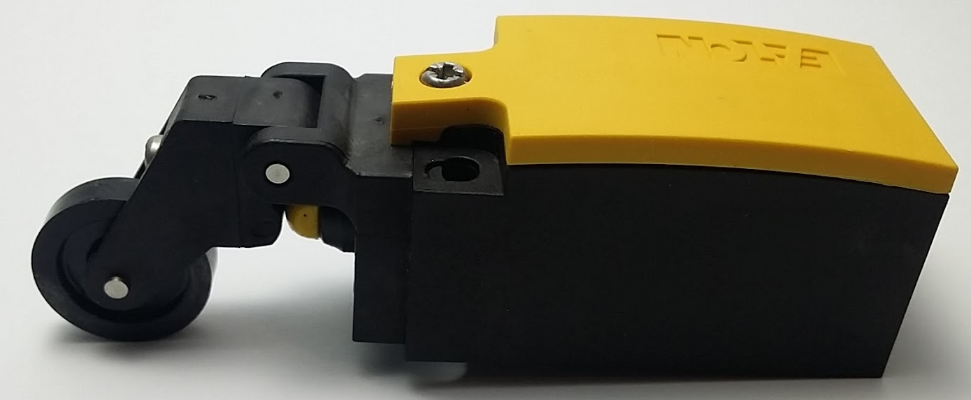
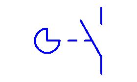
Drive – lever, handle
NAME: Actuator activated by a lever, with changeover contact
SOURCE: standard: PE-EN 60617, position (point): 2-13-11
ELECTRICAL SYMBOL DESCRIPTION:
DRIVE: lever operated drive
SPECIAL FUNCTION: none
CONTACT: The contact is switched by moving the lever.
OTHER: Such drives can be found, for example, in throttles where the rotation of the throttle turns the cam. End positions of open and closed press the roller and the contact switches.
SAMPLE APPEARANCE:
Speed, rotary motion
NAME: Speed-responsive function, rotary motion
SOURCE: standard: PE-EN 60617, position (point): 2-12-03
ELECTRICAL SYMBOL DESCRIPTION:
DRIVE: none
SPECIAL FUNCTION: Responds to speed, rotation
CONTACT: With corresponding rotational movement or speed, the NO normally open contact is activated
Limit switch
NAME: End position switch
Electronic clock, timer
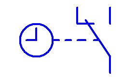
NAME: Drive with electronic clock
When the timer function is completed, the contact is switched.
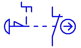
Safety button
NAME: Pushbutton, safety pushbutton, safety mushroom -like button with normally closed NC contact;
SOURCE: standard: PE-EN 60617, position (point): 2-13-08
ELECTRICAL SYMBOL DESCRIPTION:
DRIVE: safety mushroom-shaped button, manual by pressing
SPECIAL FUNCTION: not specified (no special character on dashed line); without locking
CONTACT: Normally closed NC contact. Pressing causes NC contact to open
OTHER: …
SAMPLE APPEARANCE:
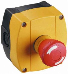
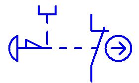
Interlocking safety button
NAME: Pushbutton, safety pushbutton, safety mushroom-shaped interlocked button being lunlocked by turning-over with normally closed NC contact;
SOURCE: standard: PE-EN 60617, position: 2-13-08 and 2-12-08 and 2-13-04
ELECTRICAL SYMBOL DESCRIPTION:
DRIVE: safety mushroom-shaped button, manual by pressing
SPECIAL FUNCTION: Interlocked (locks in position when pressed) and unlocked by turning the mushroom head
CONTACT: Normally closed NC contact. Pressing will open the NC contact and turning it will close the NC contact again
OTHER: …
SAMPLE APPEARANCE:
Interlocking safety button
NAME: Pushbutton, safety pushbutton, safety mushroom-shaped interlocked button being lunlocked by pulling-out with normally closed NC contact;
SOURCE: standard: PE-EN 60617, position: 2-13-08 and 2-12-08 and 2-13-03
ELECTRICAL SYMBOL DESCRIPTION:
DRIVE: safety mushroom-shaped button, manual by pressing
SPECIAL FUNCTION: Interlocked (locks in position when pressed) and unlocked by pulling-out the mushroom head
CONTACT: Normally closed NC contact. Pressing will open the NC contact and pulling it out will close the NC contact again
OTHER: …
SAMPLE APPEARANCE:
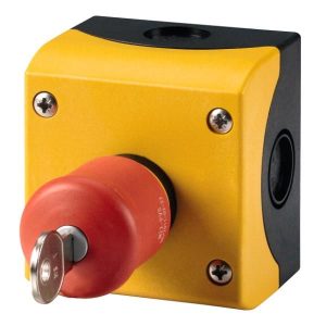
Interlocking safety button
NAME: Pushbutton, safety pushbutton, safety mushroom-shaped interlocked button being unlocked by a key with normally closed NC contact;
SOURCE: standard: PE-EN 60617, position: 2-13-08 and 2-12-08 and 2-13-13
ELECTRICAL SYMBOL DESCRIPTION:
DRIVE: safety mushroom-shaped button, manual by pressing
SPECIAL FUNCTION: Interlocked (locks in position when pressed) and unlocked by turning over the key
CONTACT: Normally closed NC contact. Pressing will open the NC contact and turning the key over will close the NC contact again
OTHER: …
SAMPLE APPEARANCE:
SPECIAL FUNCTIONS OF DRIVES:
no special function
NAME: Drive function: non-self return
SOURCE: standard: PE-EN 60617, position (point): 2-12-08
ELECTRICAL SYMBOL DESCRIPTION: Once the actuator is started, the device will remain in the started position until the actuator is acted on again (e.g., press and release)
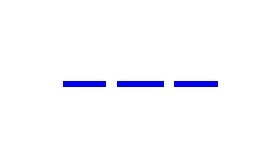
No self-return
NAME: Drive function: non-self return
SOURCE: standard: PE-EN 60617, position (point): 2-12-08
ELECTRICAL SYMBOL DESCRIPTION:
Once the actuator is started, the device will remain in the started position until the actuator is acted on again (e.g., press and release)
Automatic return
NAME: Drive function: automatic return
SOURCE: standard: PE-EN 60617, position (point): 2-12-07
ELECTRICAL SYMBOL DESCRIPTION:
Once the actuator is started, the device goes back to its return state (e.g. button, monostable switch)
Locking, latching
NAME: Drive function: locking, latching
SORCE: standard: PE-EN 60617, position (point): 2-12-12
ELECTRICAL SYMBOL DESCRIPTION:
After actuating, the drive is latched until it is unblocked by unlocking
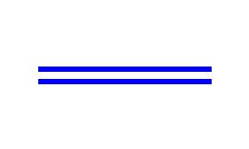
Mechanical locking of both devices
NAME: Drive function: mechanical interlock between two devices
SOURCE: standard: PE-EN 60617, position (point): 2-12-11
Direction of movement indication
Locking the device
Alternative to dashed line
Response to rotary motion