Relays are basic devices in almost every electrical and I&C installation. The principle of operation of relays is simple: driving the relay coil causes the signal to pass on through the contacts.
To begin the lesson, we need to understand how relays work, what their features and functions are. Only then can we fully understand how to read the relay symbols on the schematic.
Electrical diagrams – Operation of the electromagnetic relay
In simple terms, a relay consists of two parts: the coil and the contacts. If the solenoid is electrically activated, the contacts will close or open.
Coil – characterized by its supply voltage. To “start, trigger” an electric coil, you must supply it with either DC or AC power depending on the type of coil. The most common coils by supply voltage are:
- 12 VDC , 12 VAC,
- 24 VDC, 24 VAC,
- 230 VAC.
Contacts – are characterized by their state (open or closed) when the coil is at rest and when it is energized. In most cases, three types of contacts are used:
- NO – Normally open contact. This contact is open (does not conduct current) when the coil is not energized and closes (does conduct current) when the coil is energized.
- NC – Normally closed contact. This contact is closed when the coil is not energized and opens when the coil is energized.
- NCNO (or c/o – close/open)- a switch contact between NC and NO.
I remember the first time I ever had to deal with this and my imagination was a little lost.
Electrical diagrams – Relay schematic
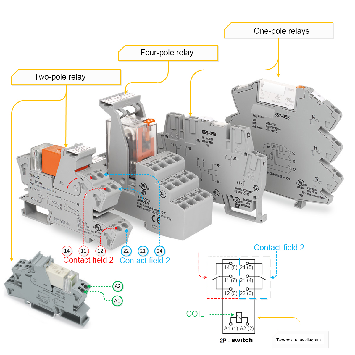
The relay symbol consists of two parts – the coil and the contacts. The coil in a relay is only one, while the contacts in a relay may be many. The number and type of contacts depends on the model of the relay. Among other things, we can distinguish:
- Single-pole relays – have one contact field, usually usually switched between NC and NO,
- two-pole relays – have 2 contact fields,
- four-pole relays – have 4 contact fields.
In a two-pole relay, applying voltage to the relay coil will trigger switching in two fields of contacts at once. The relay symbols on the wiring diagrams are shown below:
| SYMBOL | DESCRIPTION |
|---|---|
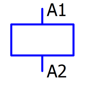 |
Relay Coil |
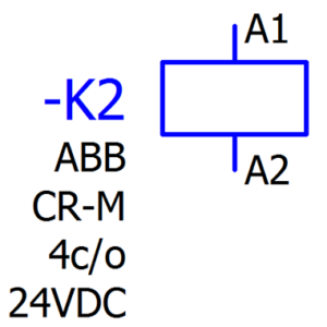 |
The coil of a solenoid relay with a description. On the left side of the coil is its unique ID name, in this case -K2. There cannot be more than one coil of a given relay on the schematic, so there cannot be two coils with the same ID. Under the ID on some schematics you can find a description to help identify the device, e.g. company, model, function, coil voltage |
 |
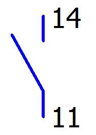
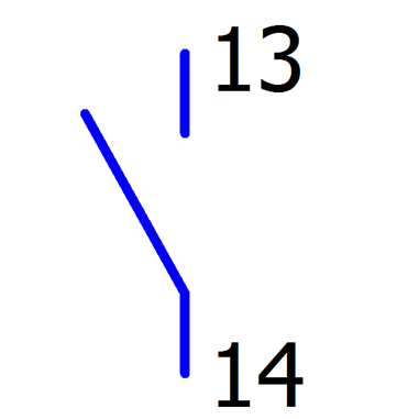
Symbol for a NC NO (or close/open) changeover contact. If the contact is drawn on the same page as the coil to which it belongs and on the same line as the coil, the contact may not have its ID drawn |
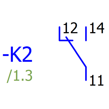 |
Symbol for NC NO changeover contact with description. The relay ID (-K2) is placed on the left side of the contact if: The contact is drawn on the same side but not to the right of the coil and not in the same line as the coil, the contact is drawn on another page, then under the ID we can find the index (/1.3 – page 1 column 3) that tells us where on the schematic we can find the coil to which this contact belongs |
|
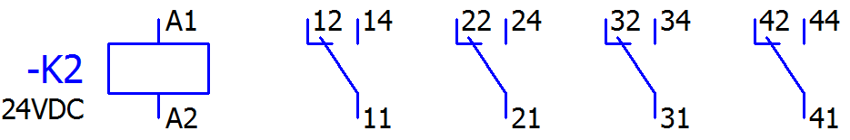
Symbols for the entire 4 field c/o relay, i.e. coil with contacts. |
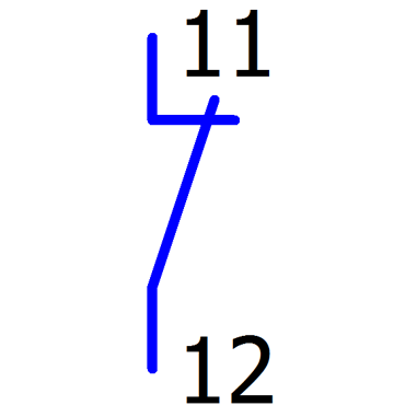 |
NC contact, normally closed, opening out contact |
 |
NO contact, normally open |
Electrical diagrams – Relays in electrical diagrams – reading
That’s right! What’s with the description normally open, normally closed. Why normally? I will try to explain. Normally – in the state before the coil is driven. The diagram must be drawn in such a way as to show the installation in the state before applying power and before performing any action in the control system (eg before pressing any button, before driving the coil, etc). The system is supplied with 24 VDC. Pressing the S1 button will drive the K2 relay and change the position of the 11,12,14 and 21,22,24 contacts:
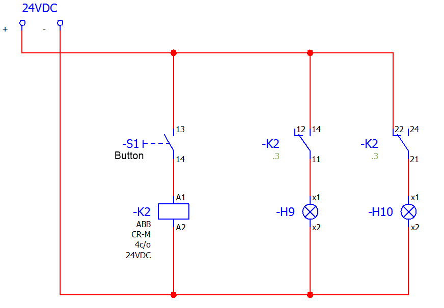
Diagram 1 shows the electrical system in a de-energized state and before any action is performed.
After applying 24VDC power to the + and – terminals:
- The coil of the relay -K2 has no power so it is not driven because the button -S1 is not pressed.
- On connections 11,12,14 the transition is only between connections 11 and 12 so the lamp -H9 has no power and does not light.
- On connections 21,22,24 the transition is only between connections 21 and 22 so the -H10 lamp has power and is lit.
After pressing the -S1 button:
- The coil of relay -K2 has power so it is energized.
- On connections 11,12,14 there is a change of transition from 11 and 12 to 11 and 14 so the lamp -H9 has power and lights
- On connections 21,22,24 there is a change of transition from 21 and 22 to 21 and 24 so the lamp -H10 has no power and does not light.
The situation is completely opposite if we change the -S1 button to NC (-S2):

If you apply power before pressing -S2, the -H9 lamp will light up immediately and the -H10 lamp will be off (because immediately after applying power the relay will work and switch the contacts). Then, when -S2 is pressed, the -H9 lamp goes off and the -H10 lamp comes on.
If this is your first time dealing with NC and NO contacts, please study these two diagrams.
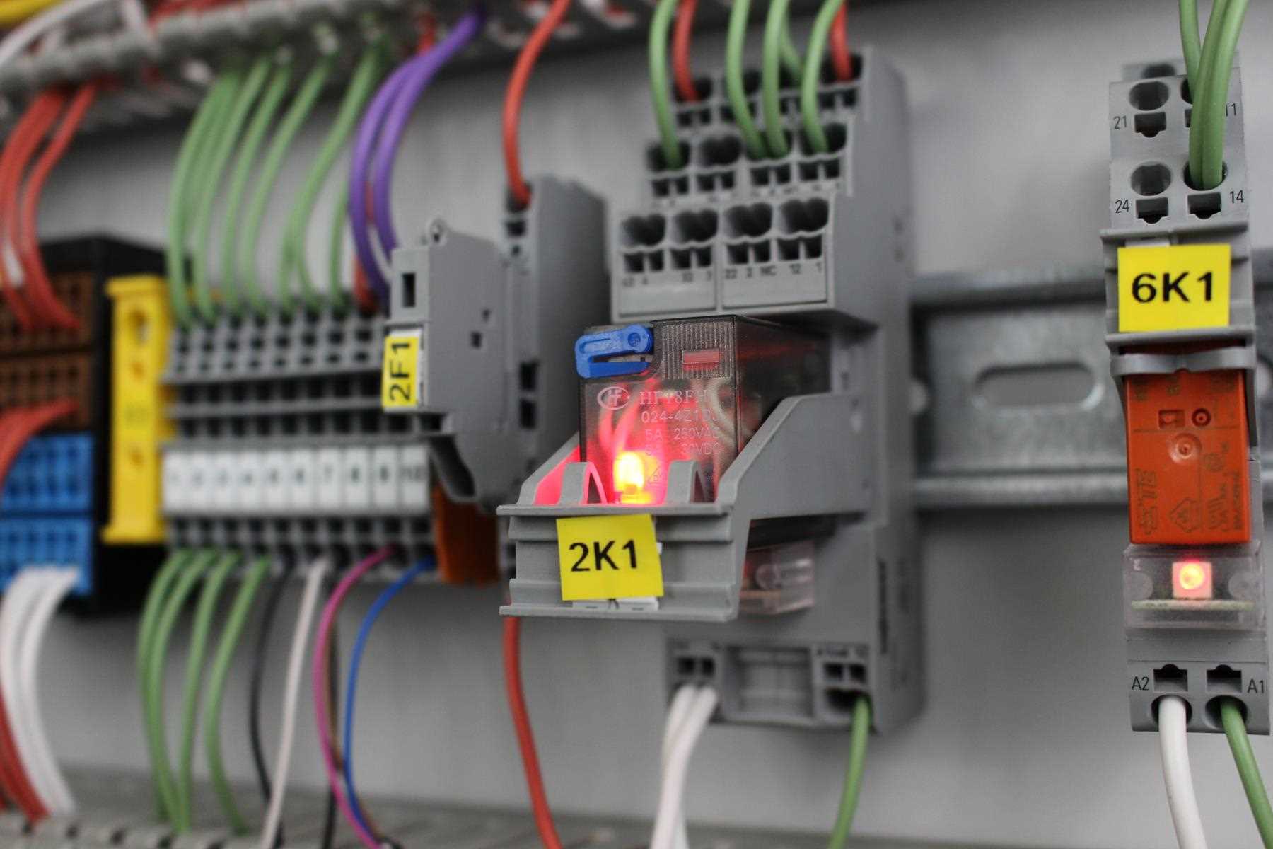
Wiring diagrams – Relays in the finished sewage pumping station schematic
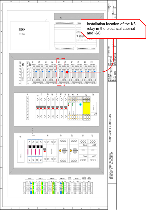
The following relay models can be found in the electrical and I&C diagram of the wastewater pumping station:
- 10 ordinary 4 pole electromagnetic relays with c/o contacts (-K1 to -K10).
- 1 time relay (-PC1)
- 1 bistable (latching) relay (-K11)
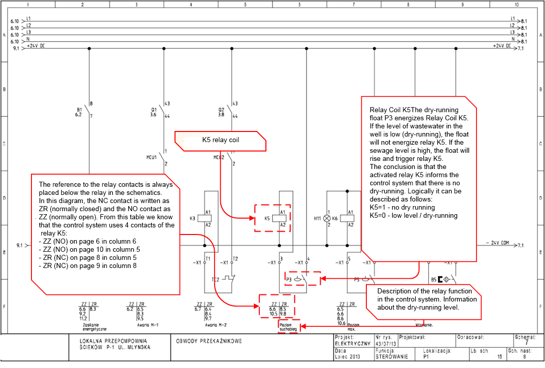
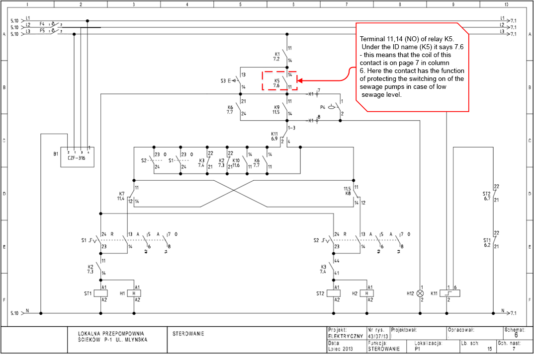
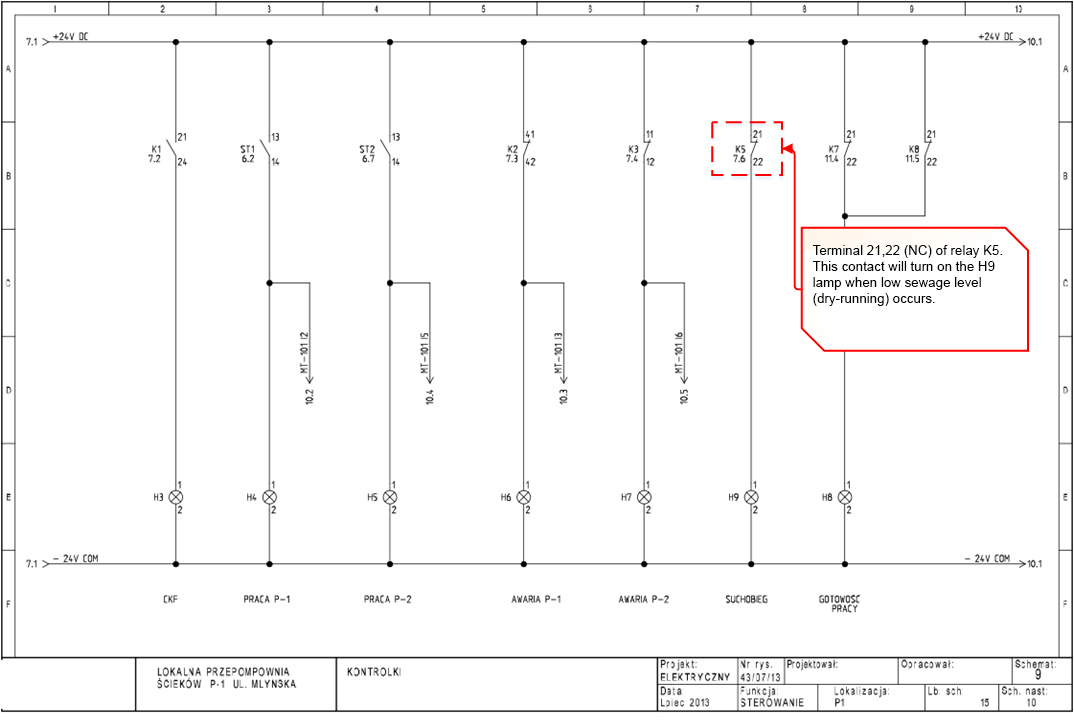
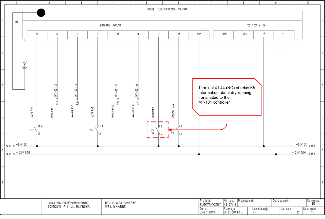
In this lesson we will focus on electromagnetic relays, from the diagram of the sewage pumping station I have chosen relay K5 for analysis. On the following slides I have explained in some detail what information we can get about it.

Electrical diagrams – Summary
It is worth noting that wiring diagrams and instrumentation diagrams may differ from each other in many respects. The appearance of the schematic depends on many factors and among others:
- on the Designer / Draughtsman and his habits, skills, knowledge and patience.
- on the environment in which the scheme is created (e.g. EPLAN, WSCAD, See Electrical, etc.)
- Designing ethics, i.e. using standards (e.g. IEC)
- dead line of finishing the project :), although there are designers and companies, who put quality above all.
For example: on the presented sewage pumping station object, four-pole relays with c/o changeover contacts were installed (changeover between NC and NO), i.e. such:
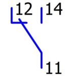
However, the diagram of the sewage pumping station shows the contacts as they were used, i.e. only connections 11,14 (connection 12 is not involved in the control system so it was omitted in the diagram).” :