The PLC in the wiring diagram in theoretical terms has been described to some extent in the previous section of this paper. However, what is theory alone without practice? I will try to show you “with my finger” on a sample electrical diagram where the PLC is located and how to read it. The examples I will present will be snippets from real wiring diagrams.
In the following examples, let’s not pay attention to what object is controlled by the PLC and focus only on the dependencies between devices.
PLC IN THE WIRING DIAGRAM – INTRODUCTION
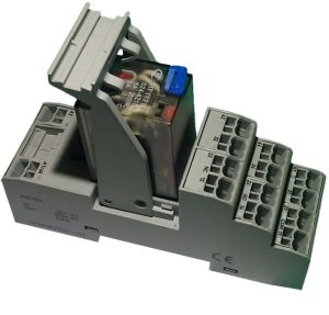
In automation wiring diagrams, one device can be shown on several pages. The first such example on this blog was described in the article “How to Read Electrical Diagrams – Relays” – where the coil and contacts of one relay were drawn on separate pages. In this case, the coil is the master part (main element – the MASTER) and the contacts are the slave part (side element – the SLAVE). The main element of a given device in the schematics should be only one, while the side elements can be many. Each part of the device both main and side can only be in one place on the diagram. Let’s see it on the example of a 4 field relay with changeover contacts.
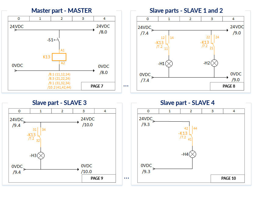
In Figure 1 I have marked one device in orange and it is a 4 pole relay. Such a relay consists of a coil (main element) and 4 contacts (side elements). Next to or below the main element in some diagrams we can find a list of links to side elements. In the example in Figure 1, a list of references for each relay contact field is shown under the coil on page 7. Please note that on the other pages, the same reference /7.2 is next to each subpart (next to the pins) – this means that the main component of the device is on page 7 in column 2.
The PLC in the automation wiring diagram is represented by the same principle. Depending on the configuration of the controller and its resources, the corresponding membership of side elements to main elements is built. In the previous Part 1 of this article, I gave an example of the composition of PLC components in a wiring diagram. In most cases, the main element of the PLC is the power supply of the CPU unit or the entire PLC including the input and output modules. Other elements are side elements. Let’s see how the theory applies in practice:
PLC IN THE WIRING DIAGRAM – EXAMPLE 1
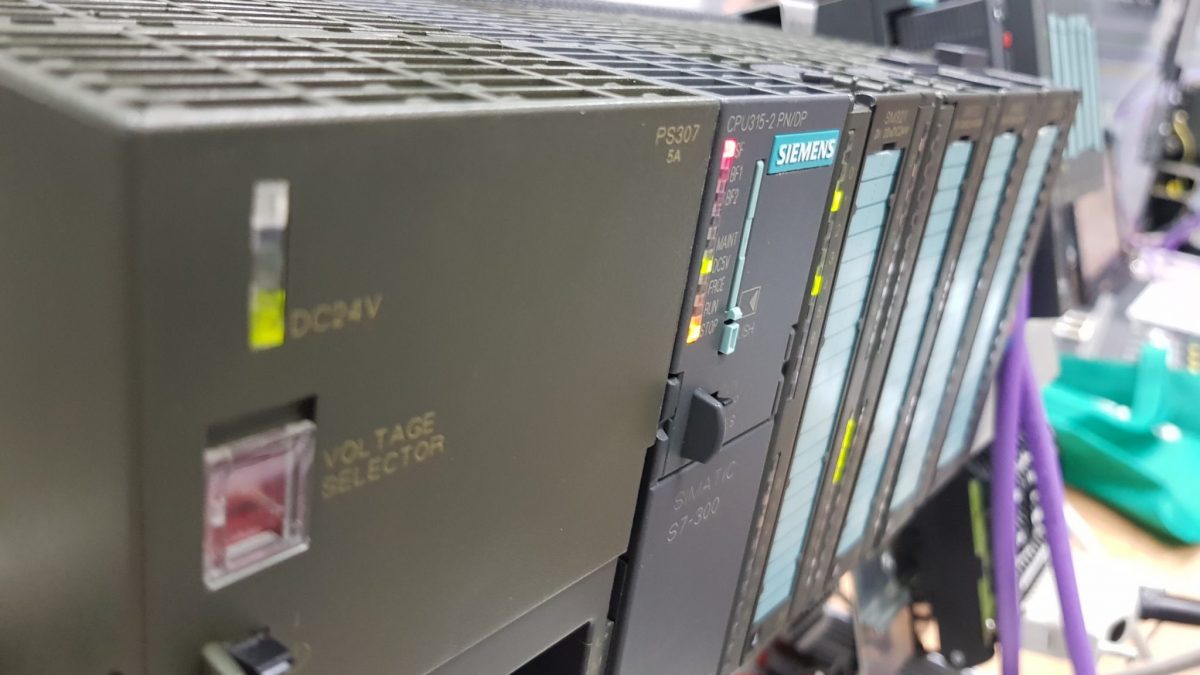
In this example, I will show you how to read a Siemens 313C-2DP PLC on a real (albeit slightly modified) automation wiring diagram. From the entire diagram, I have selected only the pages where the PLC is located – the other pages are irrelevant due to the content of this article.
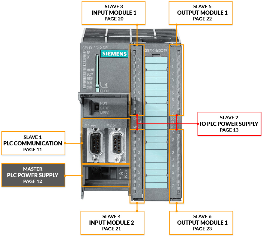
The CPU 313C-2DP controller in this example is shown in the schematic in 7 parts (Figure 2):
- Controller power supply – the main element (MASTER) all other slave elements will be assigned to this element in the schematic.
- PLC communication with other devices – side element (SLAVE).
- Input and output modules supply – this controller has 16 digital inputs divided into two “submodules” of 8 inputs each and 16 digital outputs also divided into two “submodules” of 8 outputs each. In schematics, it is common to show the power supply for all modules and submodules on one page.
- Digital input module 1 – side element (SLAVE).
- Digital input module 2 – side element (SLAVE).
- Digital output module 1 – side element (SLAVE).
- Digital output module 2 – side element (SLAVE).
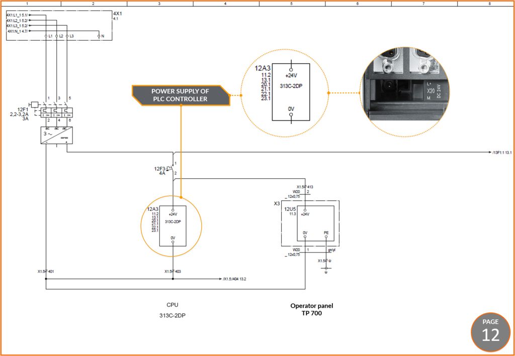
Let’s start on page 12 (Figure 3), where the main component, the PLC power supply, is located. In this example, the controller symbol is in the form of a rectangle and two terminals for connecting a 24VDC power supply. In other diagrams, such a symbol may be more elaborate – for example, it will be immediately with terminals for connecting the power supply to the input and output modules or with a listing of all digital inputs.
Note that under the controller designation [12A3] there is a list of references to the device’s side elements – the immediate conclusion is that element 12A3 from page 12 is the main element. Another note is that the driver designation begins with the number 12 (12A3) and its root element is located on page 12. This is not an accident but a practice used on many diagrams to make them easier to read. All side items must have the same designation (ID -12A3) as the main item.
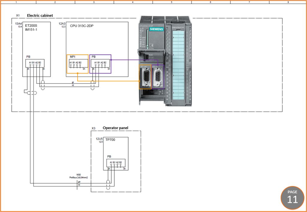
Page 11 (Figure 4) shows the communication between the devices on the PROFIBUS network. The side element of our controller responsible for communication connections on the diagram is shown as a rectangle with the corresponding connections. The designation of this element as a side element [12A3] is and must be the same as the designation of the main element from page 12. On page 11, you can also see that under 12A3 there is a link to the main element 12.3 – this means that the main element is on page 12 in column 3 (see Figure 3).
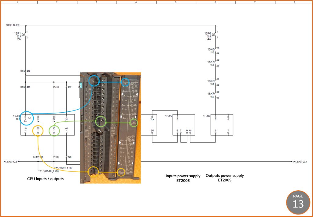
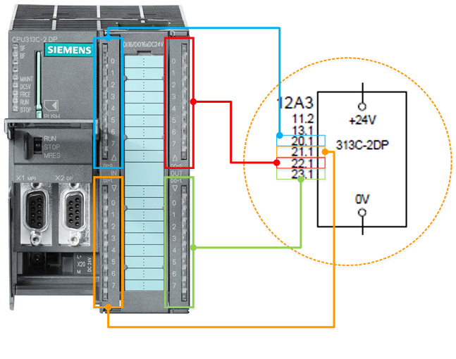
An identical designation [12A3] and reference [12.3] of the next main element can be found on page 13 (Figure 5). This part is responsible for powering the digital input and output modules of the PLC. For the modules to operate correctly, the 24VDC potential must be connected to terminals 1,21,31 and the 0V neutral potential to terminals 20,30 and 40. In Siemens controllers, after opening the IO module flap, we can see a symbolic connection diagram. In Figure 5, I have marked some terminals on the wiring diagram and the corresponding terminals on the PLC IO module.
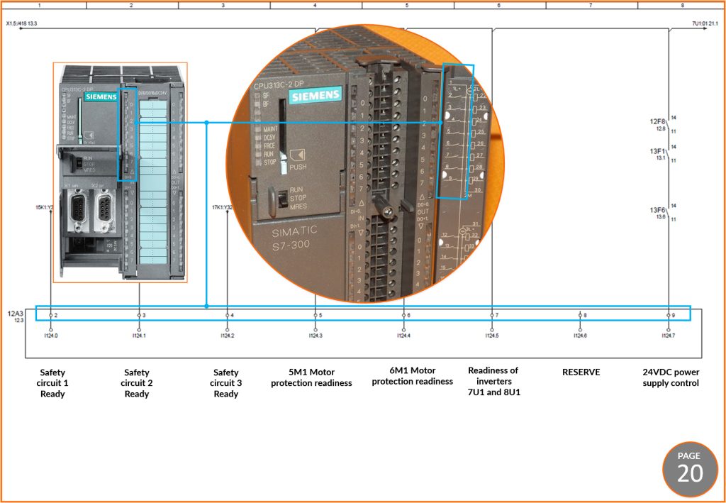
The next pages are control circuits, relay and sensor connections, etc. The next side item of the controller does not appear until page 20. Figure 6 shows the first 8 of the 16 digital inputs in module form as a side element. Let’s go back for a moment to page 12 where we can see a reference 20.1 next to the parent part – it means that on page 20 in column 1 there is another subpart – the one from Figure 6.
In the previous section of this article, I have presented ways to represent digital inputs and outputs. In this example, we see a modular representation of inputs of 8 (8 because a byte has 8 bits and is a measure closely associated with PLCs).
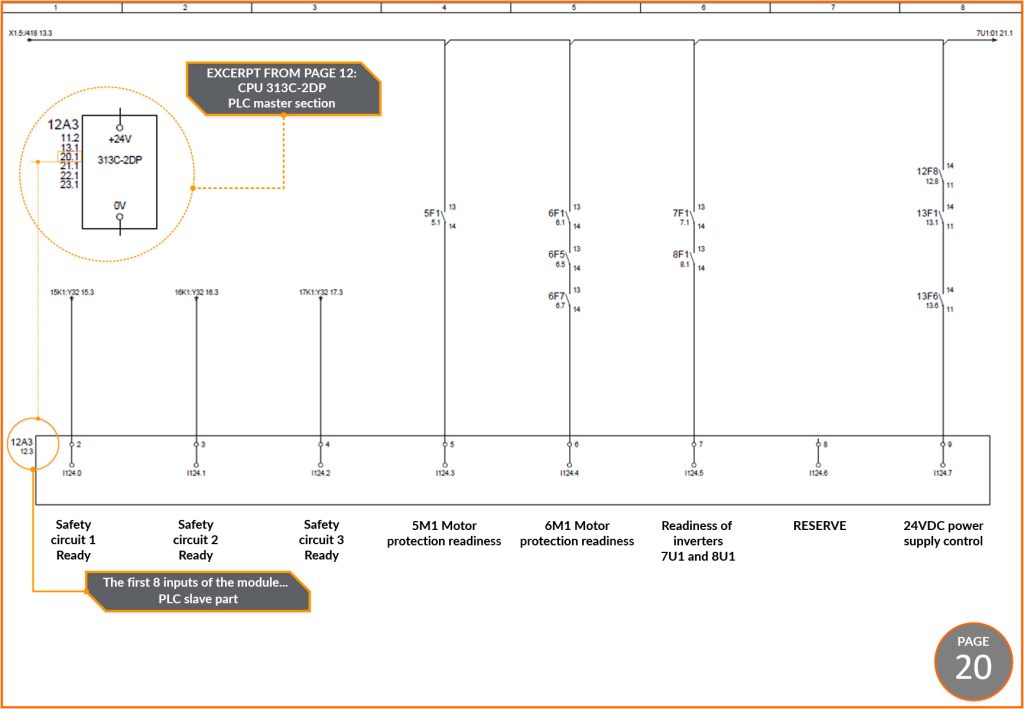
Note that the terminal numbers in the wiring diagram correspond to the terminal numbers in the PLC (see Figure 7). Assume the following failure. The message “24 V control power failure” appears on the operator panel. Upon visual inspection of the wiring diagram, it can be seen that the power control is checked at the digital input I124.7 and it is located at terminal number 9 of the PLC output input module (Figure 6 and 7). If such an alarm appears, it can be assumed that there is no 24VDC voltage at terminal 9. Since the wire is securely fastened at terminal 9, check further connections at fuses 13F6, 13F1 12F8, etc. until you find a break in the circuit from the 24 VDC source to terminal 9. In this way, most faults are found from the wiring diagram.
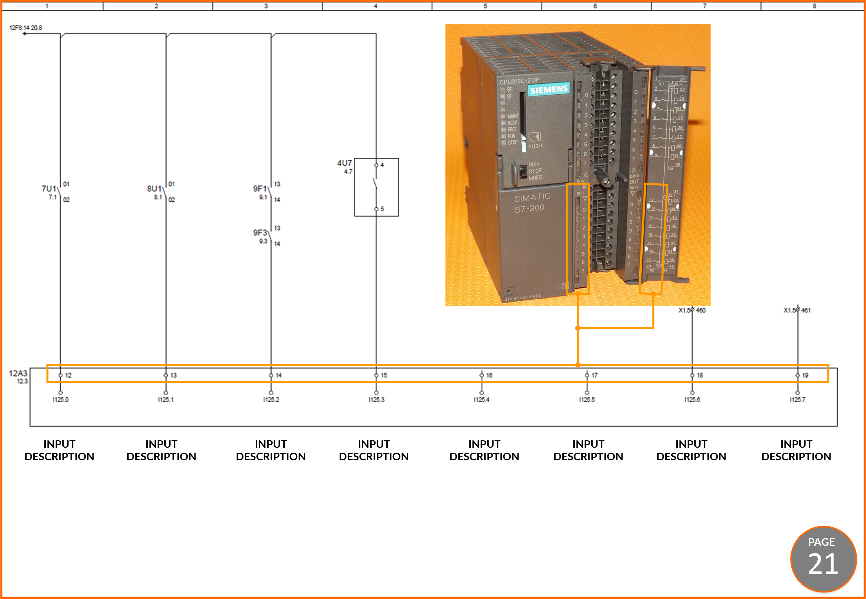
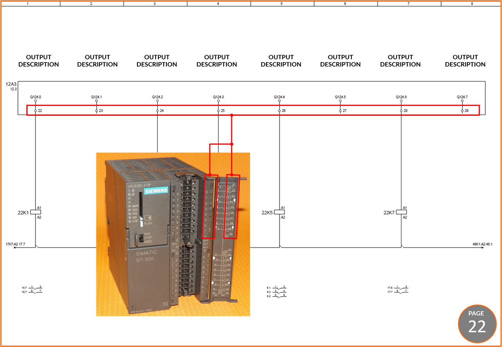
Other side elements are presented in the same way as the digital input module from page 20. So let’s take a look at Figure 8, which is a comparison of the slice from page 12, the main element, with subsequent side elements.
The following figures show the others side components of the presented PLC in the wiring diagram.

PLC CONTROLLER ON THE WIRING DIAGRAM OF THE SEWAGE PUMPING STATION
In the preface of the course I put technical documentation with wiring diagram of the entire facility which is the sewage pumping station. For practice I suggest you to download this schematic and find on it the controller (MT-101). Then try to find information about it on the internet (pictures, schematics, etc.) and compare it with the downloaded wiring diagram. The presentation of the controller used in this sewage pumping station differs slightly from the one in this article, but I think you will do just fine.