I remember in my senior year of college when I started looking for a job within my field of study. I found an ad for a company that remanufactures waste reduction machines, among other things. They were looking for a man – a “handyman”, self-taught, automatic, electrician, call him what you will, but in general, to be able to fix a simple machine. So I call them. I find out what the job entails, I show off to my future boss what a fantastic man I am, and at the end of the conversation I hear more or less that:
“Well, you come by tomorrow and try to fix one machine. You’ll get a diagram and all the tools you need.”
Brilliant! My first job interview! After a while, it eventually realized myself that I did not understand electrical schematics after all. Well, I guess there was something abuot that there at university. Maybe some wiring diagram or individual symbols between classes came up. But my knowledge on the subject was very poor. Generally no panic, we’ll just ask Google how to read a wiring diagram and the next day the job will be mine! When to my disappointment it turns out that there is little information on the subject. Unfortunately, this is also the case today.
Therefore, my dears, I have decided to put all my efforts into developing a course under the title:
“How to read schematics of electrical circuit and diagrams of Control and Measurement Instruments and Automation”
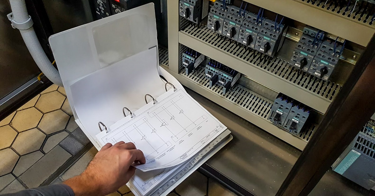
Reading wiring diagrams is not easy for people who have not dealt with electrical and instrumentation equipment. Learning the names of the symbols alone will do little if you are not familiar with the device. In developing the course, I will try to illustrate and explain as much as possible. We’ll start with the simplest issues, such as the connector, terminal, and connections. I’ll take the simple electrical schematics first. For the sake of people who, like me, knew little about schematic reading at the beginning of their career, I will start the course with the basics. I’ll try to describe it in a way that I wish I had found before my first job.
Download wiring diagram
You will need a sample diagram for the course. On the net I found a diagram of electrical and Control and
Measurement Instruments and Automation of a sewage pumping station. I think enough to start with.
Documentation also includes description and drawings.
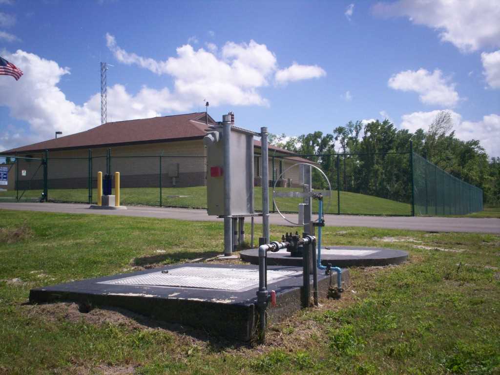
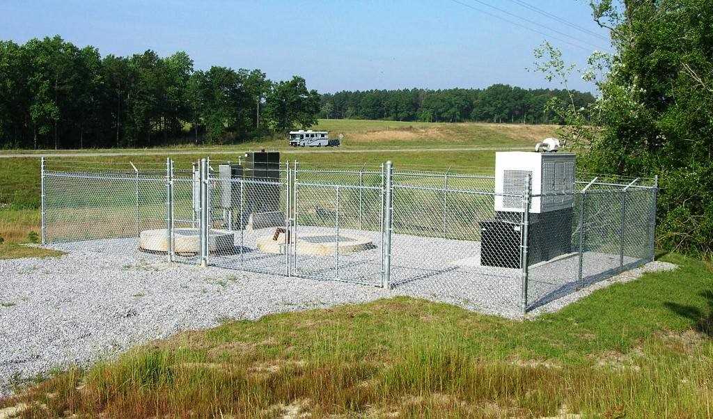
Electrical schematics – object for schematic reading course – wastewater pumping station
We will be based on the electrical schematic of the facility, which is a sewage pumping station. It is a simple control system in terms of automation. In the technical documentation (DTR) in points 12.4 and 12.5 you will find a description of the operation of this system object in manual and automatic mode.
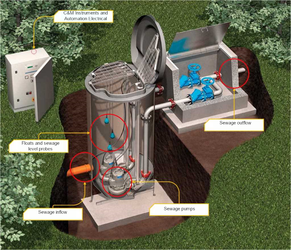
Wastewater measurement
Measuring the sewage in the pumping chamber is done by installing three MAC-3 float circuit breakers at appropriate levels (digital measurement, status 0 or 1) and a hydrostatic probe (analogue measurement). The hydrostatic measurement in cooperation with the controller realizes the control algorithm of the pumps, moreover, it also defines the alarm levels and ranges in which the work of the pumps is prohibited. As an alternative to the unreliability of the system, it was introduced the parallel work of the pumps in the automatic system, controlled from the floats, with full protection against running dry and signaling the maximum level.
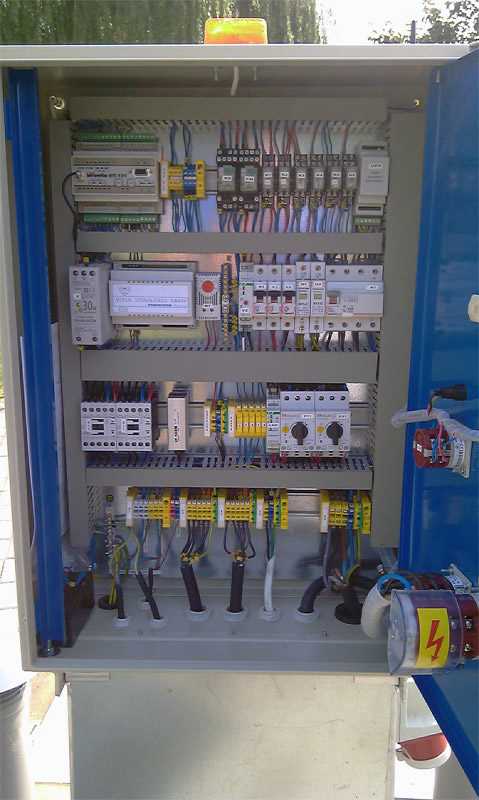
Waste water level indication is visible on OC-11 converter.
The signaling status from the level measurements can be seen on the door and are as follows:
- min. level red – pumping station chamber empty
- max. level red – max. level exceeded
The external visual signaling is immediately switched on when the max. level or the min. level is reached. The visual indication will remain active until all alarms have ceased.
Manual operation
In manual operation, the user decides when and which pump should be switched on. All protections discussed in automatic operation are active except for level measurement. When the pumps are switched to manual pumping, the pumps run until the minimum level is reached. For maintenance or repair purposes, and when it is necessary to completely empty the chamber of wastewater, the user may pump down the wastewater completely by pressing the PUMP REPAIR OPERATION button and immediately the pump will continue to pump until the button is released. The pumping stations must not be left running in manual operation because the operation control protections from the sewage level are not implemented, which can lead to permanent damage to the pump.
Automated operation
The control system of the two pumps is implemented through the automation system. Automatic control is responsible for maintaining a constant level in the pumping station chamber, and dealing with disturbances and alarm situations according to the installed switching capabilities. The whole system implements the algorithm of switching off and on the pumps observing the following rules:
- alternation of operation of pumps
- switching on the appropriate number of pumps depending on the level of sewage reached
The automation system receives signals that influence the correct operation of the pumping station:
- level measurement
- pump protections status
- Status of circuit breakers for pumps approved for automatic operation
- monitoring the state of the power grid
Any alarm signal is immediately analyzed by the automatic control system, which will decide on the operation of the pumps according to the program guidelines. At the same time, a light alarm signal will be generated ( flashing light on the control cabinet ). In an automatic system, the operator only has to switch the circuit breakers of individual pumps to automatic operation. The entire task is controlled and managed by the automation system according to the above mentioned issues.