The article is a summary of the most commonly used safety devices and their symbols in electrical and automation installations. This will help you learn the markings on the wiring diagrams.
At the beginning of this article, I will give a general overview of the elements that make up security symbols. Next, I will try to explain the operation of the following security features:
- Overcurrent circuit breaker,
- Residual Current Device,
- Motor circuit breaker,
Electrical Symbols – DEVICE SYMBOLS – COMPONENTS
| Symbol | Name | Description | Sample Appearance |
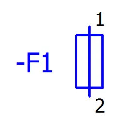 |
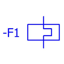
Fuse, general symbol | Breakage of the circuit by melting the fuse core occurs after a specified time for a given current. | 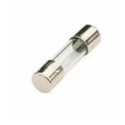 |
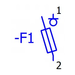 |
Single-pole fuse insulating switch | Disconnector switch that contains a fuse base. | 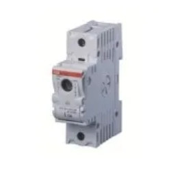 |
 |
Thermal trigger | The thermal trigger provides overload protection for the load. Used, for example, in motor circuit breakers. | 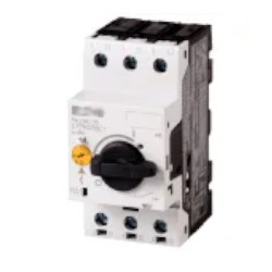 |
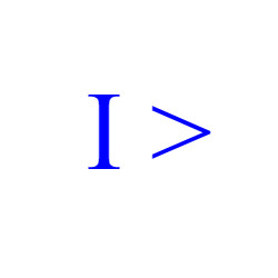 |
Overcurrent triggering | The thermal trigger provides short-circuit protection. Used, for example, in motor circuit breakers | |
 |
Overvoltage triggering | Activation when voltage is exceeded. | Used in special protecting devices. |
 |
Undervoltage triggering | Activation after voltage reduction. | Used in special protecting devices. |
 |
Zero-voltage triggering | Activation after voltage is lost. | Used in special protecting devices. |
 |
Residual current triggering | Used in residual current circuit breakers | 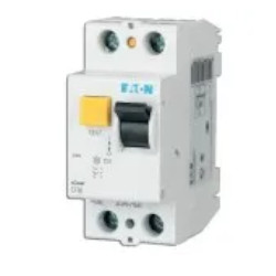 |
 |
Lock with mechanical interlock (switch) | General symbol for lock in protection devices | Used in special protecting devices. |
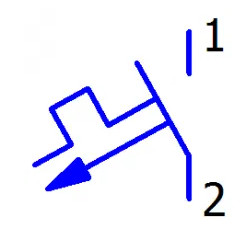
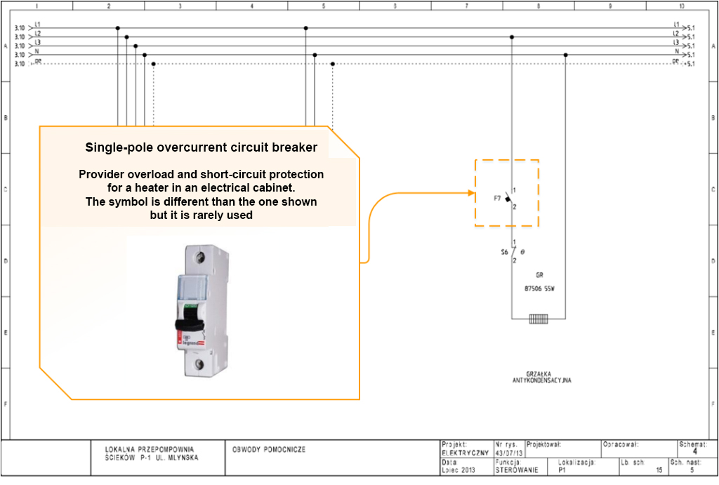
Electrical Symbols – OVERCURREMT CIRCUIT BREAKER
Circuit breaker (overcurrent circuit breaker, installation circuit breaker type DS) – an element of electrical installation, which breaks the circuit when the current flowing in the circuit exceeds the safe value for this circuit. These circuit breakers are intended for control and protection against overloads (overloads and short circuits) of load circuits of electrical installations and equipment in households and other places.[wiki]
| Symbol | Name | Description | Sample Appearance |
 |
Residual current device – 2-pole | Protection against electric shock in single-phase installations |  |
 |
Residual current device 4-pole |
Protection against electric shock in three-phase installations | 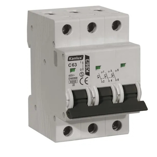 |
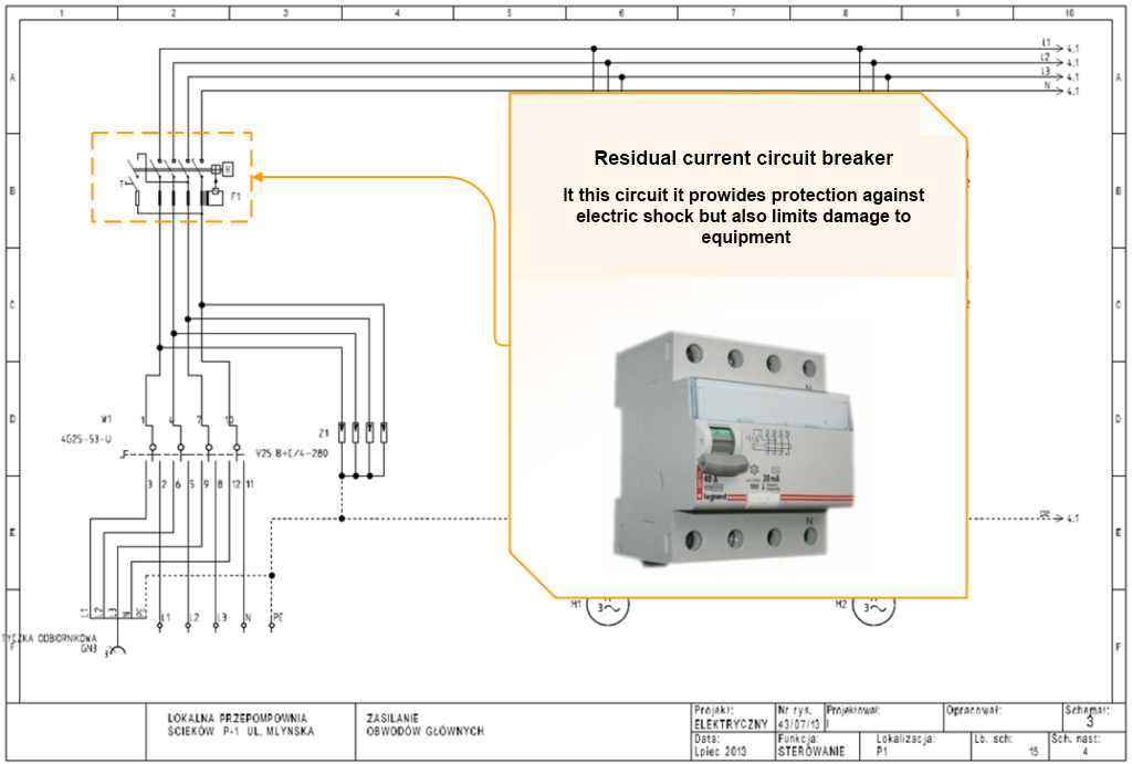
Electrical Symbols – RESIDUAL CURRENT DEVICE
Residual Current Device – electrical protection, a device that breakes the circuit when it detects that the electrical current flowing out of the circuit is not equal to the incoming current. Used to extend the protection of people from electric shock at direct and indirect contact, it also limits the effects of damage to equipment, including causing a fire.
In the video below, a YouTube user performs a simple test of how a residual current circuit breaker works. The resistor symbolizes a person and the current flowing through it (electric shock). A residual current circuit breaker disconnects the power supply almost immediately when it detects a leak of current:
| Symbol | Name | Description | Sample Appearance |
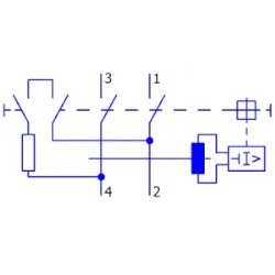 |
Residual current device – 2-pole | Protection against electric shock in single-phase installations |  |
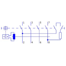 |
Residual current device – 4-pole |
Protection against electric shock in three-phase installations | 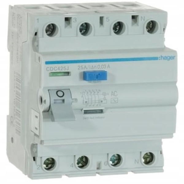 |
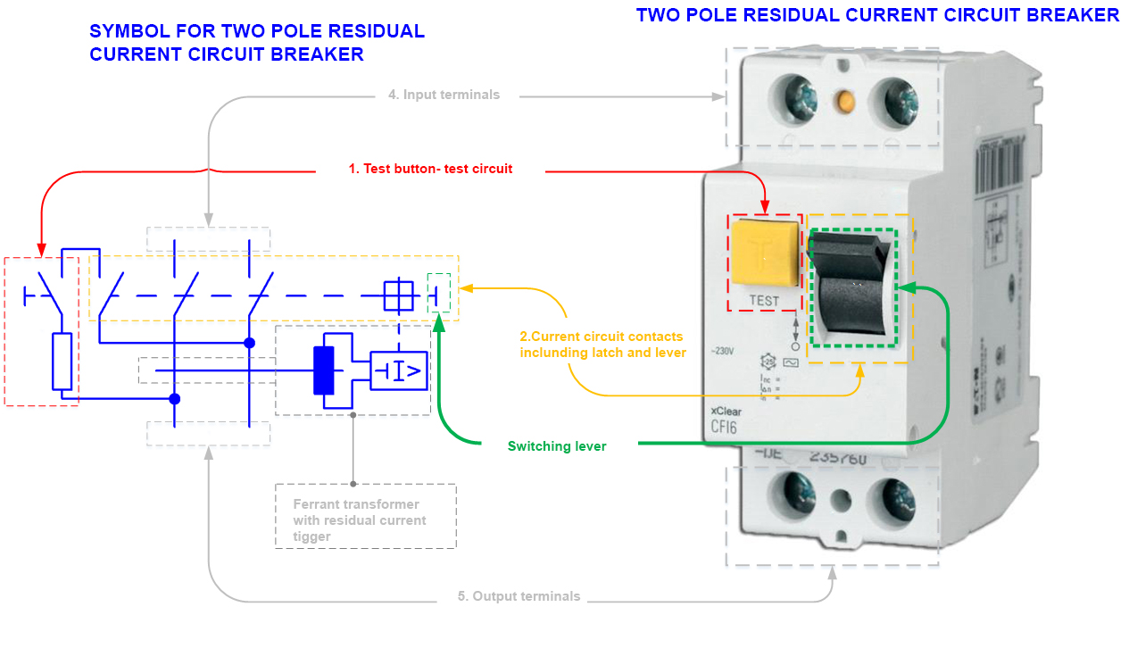
Construction of a residual current device (see Figure 1):
- Residual Current Device test button – allows the RCD to be tested while under electrical voltage.
- Current path contacts including latch and switching lever. The residual current trigger disconnects the current path contacts with a mechanical latch and causes the lever to drop.
- Switching lever.
- Input terminals (stationary part of the contacts).
- Output terminals.
- Ferranti transformer with residual current trigger.
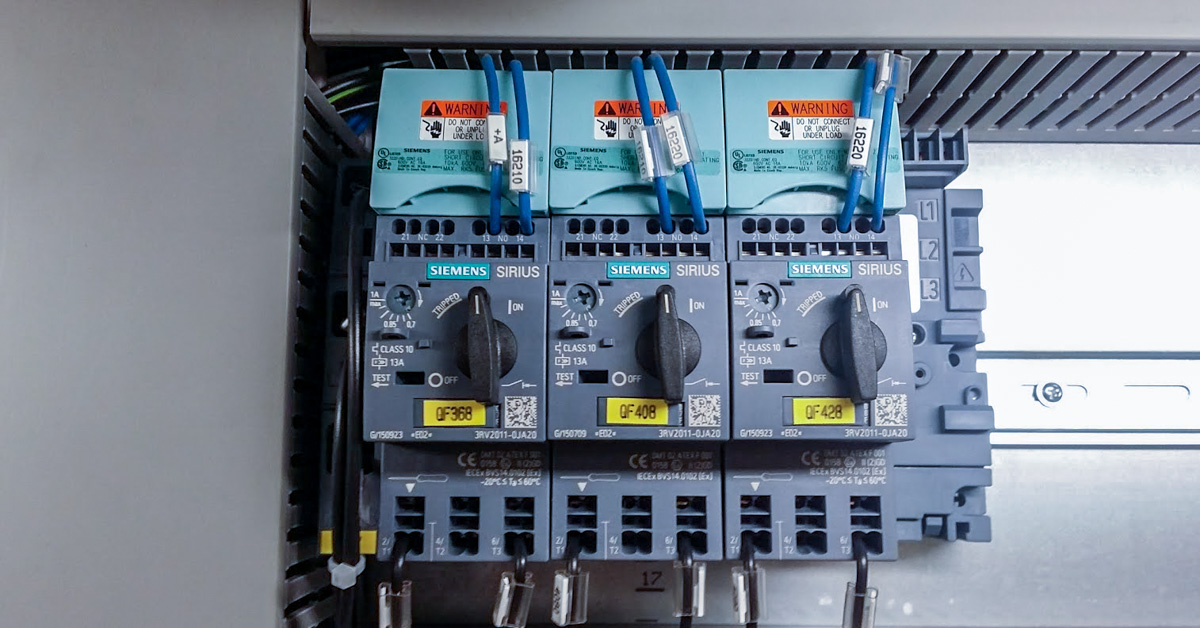
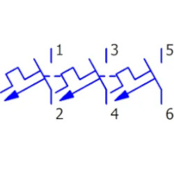
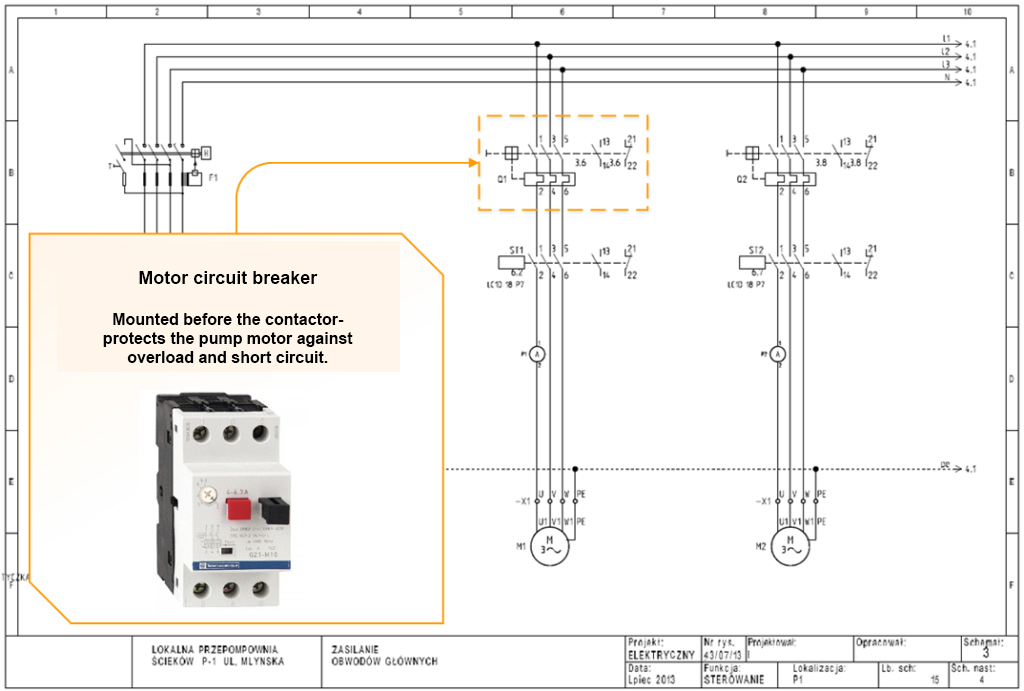
Electrical Symbols – MOTOR CIRCUIT BREAKER
Motor circuit breakers are components for connecting, protecting and separating current circuits primarily loads with motors. At the same time, they protect these motors from damage due to blocked starting, overload, short-circuit and single-phase failure in three-phase networks. They have a thermal trigger to protect the motor winding (overload protection) and an electromagnetic trigger (short circuit protection).
| Symbol | Name | Description | Sample Appearance |
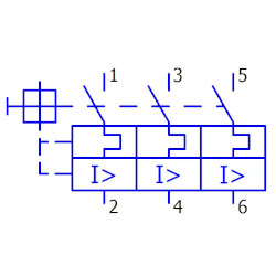 |
Motor circuit breaker | Motor overload and short circuit protection | 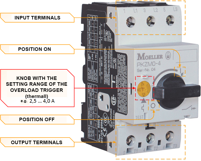 |
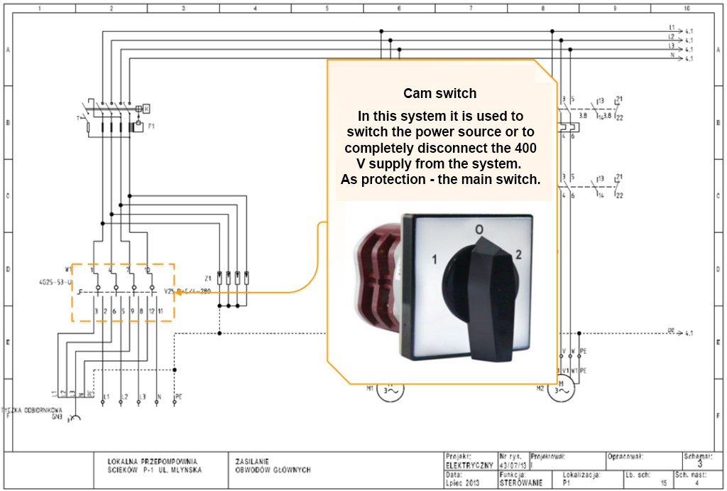
SECURITY FEATURES IN THE ELECTRICAL SCHEME
Download wiring diagram
You will need a sample diagram for the course. On the net I found a diagram of electrical and Control and
Measurement Instruments and Automation of a sewage pumping station. I think enough to start with.
Documentation also includes description and drawings.
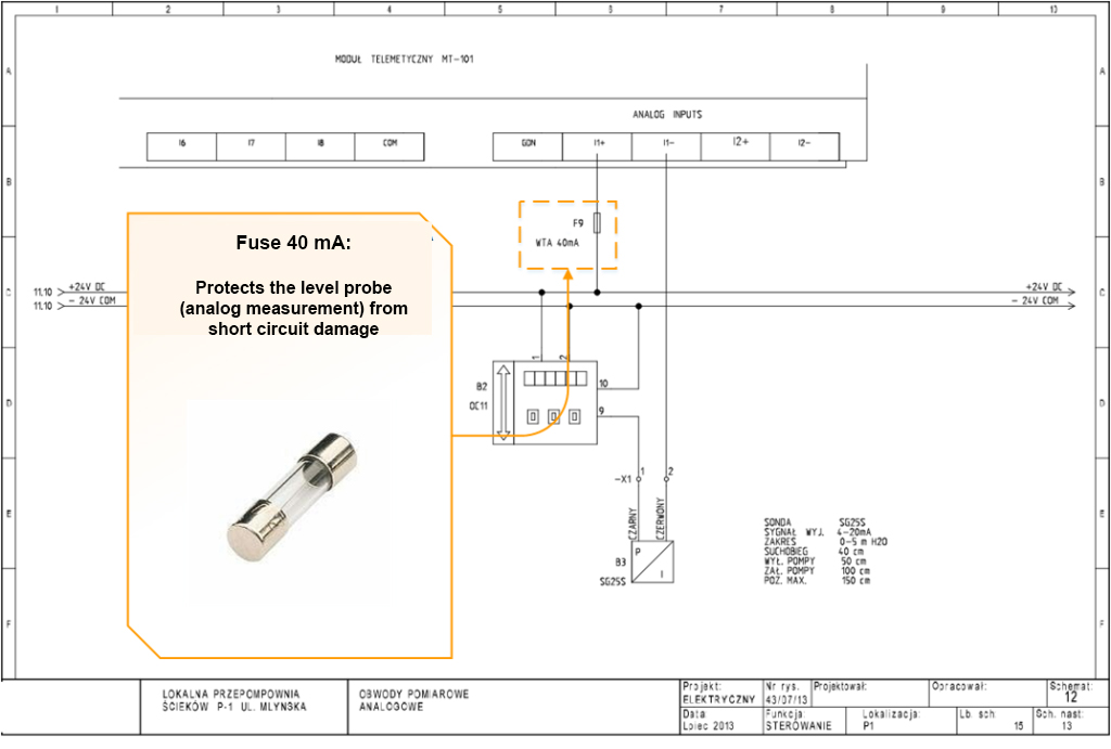
Below I put the marked protective devices on the finished diagram of the sewage pumping station.
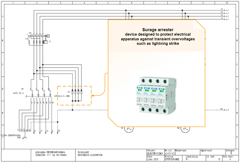


A book of several volumes could be written on the subject of protection measures. On Internet forums, experts shout each other down answering security-related questions and pointing out irregularities. The topic of security selection is extremely complicated, so if you notice somewhere an error in the article, please write it in the comments or in an e-mail.