This paper continues the lesson of analyzing contact control systems. This time we will focus on the automatic control based on the ready-made electrical scheme of the sewage pumping station.
In the previous lesson, I covered manual control quite thoroughly using the same wiring diagram that we will build on in this lesson. Therefore, I recommend that you read the previous lesson beforehand.
Download wiring diagram
You will need a sample diagram for the course. On the net I found a diagram of electrical and Control and
Measurement Instruments and Automation of a sewage pumping station. I think enough to start with.
Documentation also includes description and drawings.
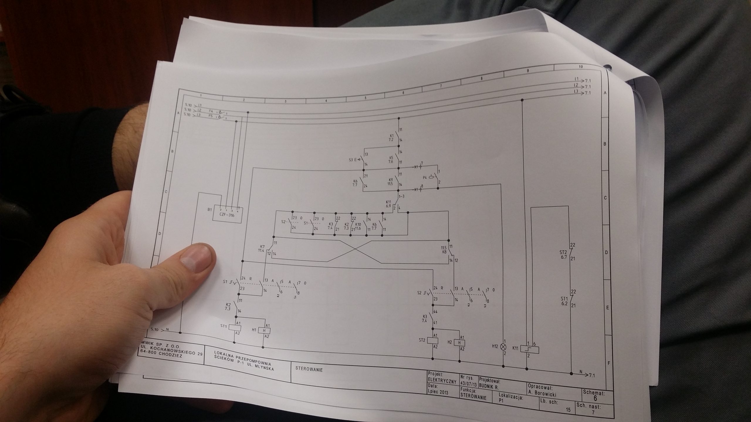
You will be most comfortable in this lesson if you print out the diagram from the link above. We will be analyzing a control system that has references to multiple pages of the electrical schematic. Remember, this article shows you how to analyze a wiring diagram, so you don’t need to know the exact object we’re basing this on.
#0 Introduction – a reminder from the previous lesson #5
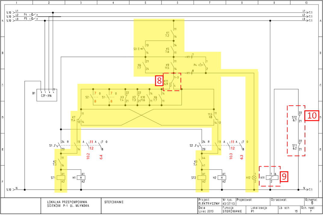
We will base this on page 6 of the wastewater pumping station wiring diagram (Figure 1). The site is divided into two areas: manual control and automatic control. In the previous lesson the rules for finding drives for contacts were explained, so now when explaining automatic control I will only use verbal description. Following the content of the article, try searching for devices on your own on different pages.
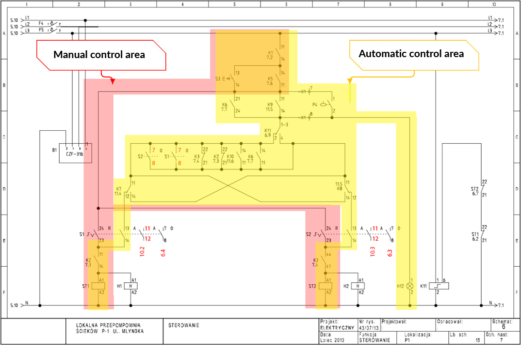
As you can see from the figure above, some pins belong to both control areas. This means that the same conditions must be met for both manual and automatic control. Starting to analyze the connections from above will be the following conditions (see Figure 2):
- [1] Connection of 230 V to terminal 11 of relay contact K1,
- [2] The correctness of the 400V power supply – we know from the previous lesson that contact K1 belongs to relay K1, whose coil is shown on page 7 in column 2. Coil K1 is energized by device contact B1 – CKF (Phase control sensor CKF-316. This sensor disconnects contact 7,8 when it detects a loss in at least one of any phase (L1, L2 or L3) or voltage asymmetry between phases. The purpose of this device is to protect the pump motors from starting at an inadequate voltage). (page 6 column 2),
- [3] Waste water level must be greater than dry running level; dry running float P3 must be up (relay K5 – page 7 column 6 activated), or [4] S3 button is pressed,
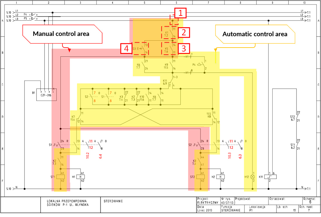
#1 Automatic Control – Wastewater Pump Startup Conditions
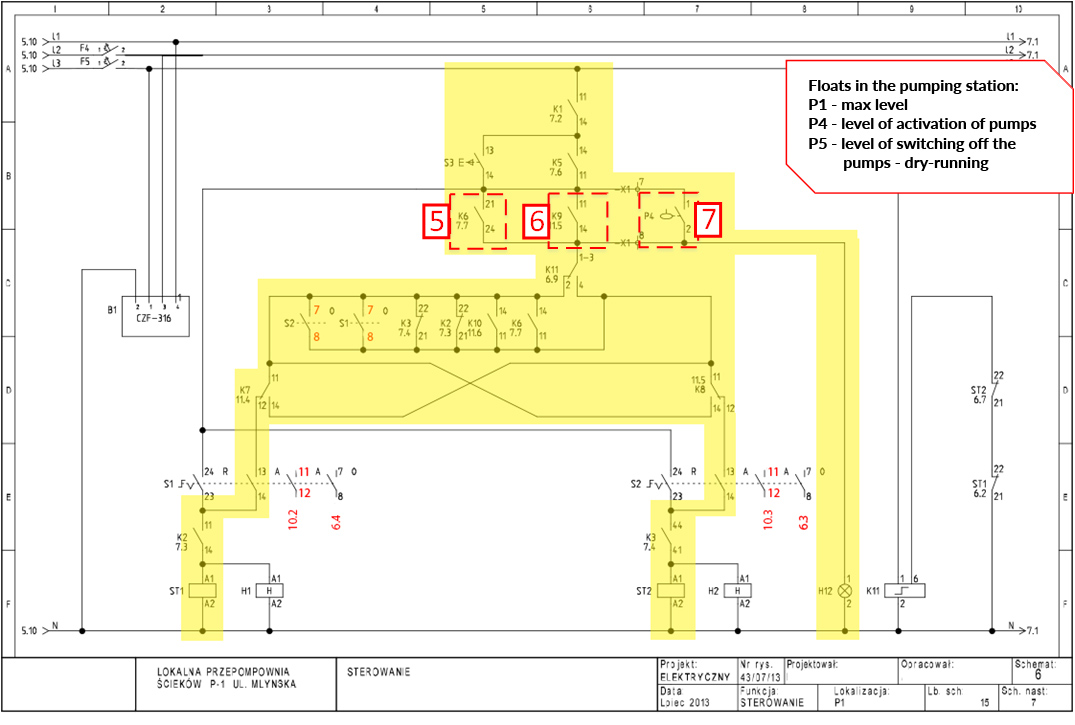
In Figure 3 I have marked 3 contacts that decide to switch on the pumps in automatic control mode (passing the voltage further to terminals 1-3 of the bistable relay):
- [5] Wastewater raised float P5 – On page 7.7, float max P5 turns on relay coil K6 and turns on alarm level warning light H11.
- [6] MT101 controller switches on relay K9 – The programmable controller switches on the first pump with output Q7 via relay K9 (page 11.5) based on the analog measurement from probe B3 (page 12.6). On and off levels are configured in this controller. For example, at a sewage level of 3000mm, the controller will switch on the pumps at output Q7 and below the level of 1200mm it will switch them off by disconnecting the voltage from output Q7.
- [7] Wastewater raised P4 switching float – The switch-on float is typically located between the max P5 alarm float and the switch-on level from the programmable controller. Float P4 does not activate any additional relay, it was directly plugged into this control system.
#2 Automatic Control Systems – Alternating Operation of Wastewater Pumps
In sewage pumping stations, in failure free condition, the pumps operate alternately. This function is implemented differently depending on the devices used. In this case, a bistable relay is used, which switches its auxiliary contact upon detecting a pulse applied to its coil. In our system, the alternating operation of the pumps works as follows:
After the first time the power is turned on and after every time the pumps are turned off [10] the relay K11 is energized [9], which will switch contact 1-3,2,4 [8].
When any of the pumps is running, the control circuit of the relay K11 will be disconnected [9] by the auxiliary contacts of the contactors ST1 or ST2 [10]. After pumping is finished, contactors ST1 and ST2 will be switched off, and additional contacts ST1 21,22 and ST2 21,22 [10] will remain closed, which will switch contacts of relay K11 [8].
#3 Automatic control – Attaching a second pump
As I wrote above, the pumping station in normal trouble-free operation turns on the pumps alternately and only one pump works to pump out the sewage. The other thing is when there is a failure, for example, the motor of pump 1 is damaged and the relay K11 in the position to switch on the pump P1 – then the system will connect the pump P2.
Eh, I could write a thousand words about it or just draw it :). I always say that a drawing explains more than words. So let’s analyze the two drawings below showing the situation of automatic control and motor failure of the pump P2 – assume that the relay contact K11 is set to switch on the contactor ST2 – the pump P2.
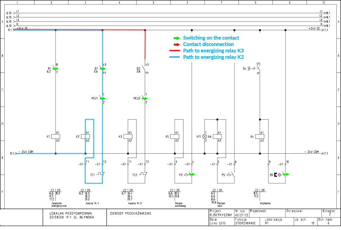
Figure 5 shows the 7th page of the wiring diagram. If the motor circuit breaker Q2 detects a motor fault, it will disconnect the main power circuit to the pump motor P2. Also the auxiliary contact Q2 will be disconnected so the relay K3 will not be energized. Pump P1 is not in a failed state and relay K2 is energized. We assume this situation and return to page 6 of the wiring diagram:
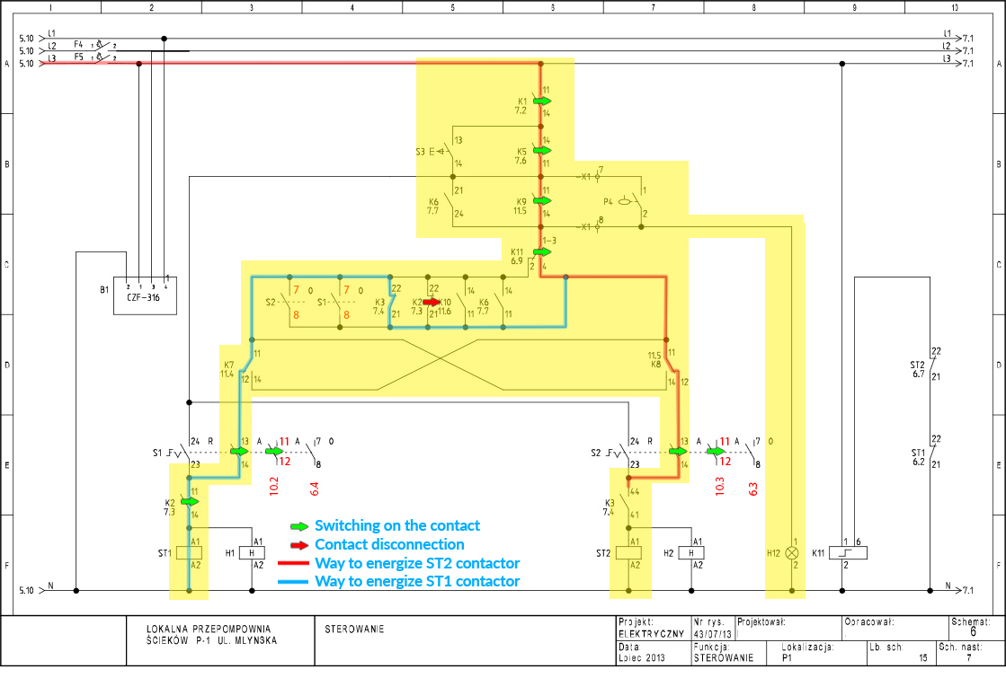
In Figure 6, I have highlighted two paths, the first to switch on contactor ST2 (red) and the second to switch on contactor ST1 (blue).
Let’s start with the red path:
- [F5] – the overcurrent circuit breaker (“es”) is on,
- [K1] – CKF (B1) has not detected any abnormality in the 400V power supply so contact K1 is on,
- [K5] – float P3 is up; there is no dry-running so the K5 contact is on,
- [K9] – MT101 controller based on analog level probe B3 (SG25S) activates relay K9,
- [K11] – Bistable relay is activated for pump P2 due to alternate operation,
- [K8] – MT101 has built-in GPRS modem, so there is possibility of remote management of the controller – relays K7 and K8 are used to remotely disable activation of the pumps. We assume that relays K7 and K8 are not switched on,
- [S2] – the MANUAL/0/AUTO switch is in auto position,
- [K3] – from Figure 5 we know that the pump P2 is in failure so the contact of relay K3 will be disconnected. This is where the path to switch on the contactor (P2 pump) ends.
Let us see the blue path:
Since the relay K3 is not switched on, its NC contacts will remain at rest. This means that the contactor [ST1] will be switched on via contact [K3 21,22], contact [K7], switch [S1] and contact [K2].
An analogous situation will occur if pump P1 fails and pump P2 is operational. Pump P2 will be switched on by NC contact K2 21,22.
I leave the subsequent pump attachment functions to you to investigate on your own. I encourage discussion in the comment section. If something is unclear then feel free to write about it in the comments. I will try to respond as soon as I can.