PLC is used in almost every automation system these days. In wiring diagrams, the representation of a PLC can be realized in several ways, although similar to each other. In confronting this topic I will try to explain as much as possible.
Download wiring diagram
You will need a sample diagram for the course. On the net I found a diagram of electrical and Control and
Measurement Instruments and Automation of a sewage pumping station. I think enough to start with.
Documentation also includes description and drawings.
Introduction
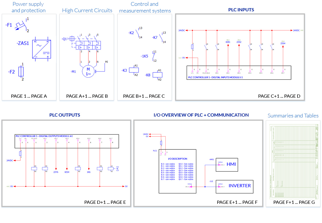
Most simple wiring diagrams are constructed very similarly. Typically, such diagrams consist of a cluster of the basic functions of an object and its control system:
- Power supply and protection.
- High Current Circuits.
- Control and measurement systems.
- PLC Inputs.
- PLC outputs.
- I/O overview of PLC + communication.
- Summaries and Tables.
While the order may vary, in many cases this is how it goes. To make you assimilate this more I have prepared a drawing that briefly illustrates the construction of a simple electrical diagram:
PLC in the wiring diagram
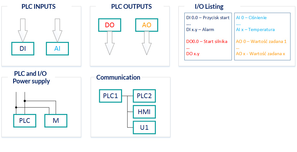
A PLC in a wiring diagram may consist of several components:
- Digital and analog inputs.
- Digital and analog outputs.
- Input/Output List.
- Power supply for the PLC and its modules.
- Communication links.
The configuration and order of the PLC components listed above depends on many factors. Large wiring diagrams may contain all or even more of these components, while smaller ones may consist of only a few. The order and style of presentation of PLC components, in turn, depends on the designer’s habits, the company’s standard, and the program in which the electrical documentation is created (e.g., Eplan, WSCAD, See Electrical, etc.).
I/O in the wiring diagrams
What is this I/O? From the English language Input/Output. I/O on wiring diagrams is represented in many ways. I honestly feel that each diagram is drawn in a different program and style. Why does this happen? Not only are there many programs available to help you draw the schematics, but each of them provides several ways to represent inputs and outputs of the PLC or its I/O modules.
Inputs – Digital or analog inputs come from the input devices and are converted into logic signals understood by the PLC. The digital input to the PLC will be a binary state of 0 or 1 while the analog input will be stored in the controller register as a range of numbers e.g. 0 to 27684.
Outputs – digital or analog outputs are controlled by the PLC to a form that can be used to control devices (actuators).
PLC inputs
One representation of PLC inputs in wiring diagrams is to divide the inputs into modules and place them on one side. Such a module usually consists of 8 inputs, although there are also 4,16 and 32 inputs or others.
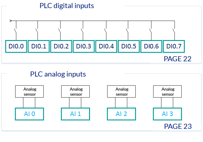
The input is almost always drawn with the connection facing up, i.e., the signal to the PLC input is drawn from the top to the input (see Figure 3). However, one should be careful because, although rare, there are various creative inventions in the diagrams.
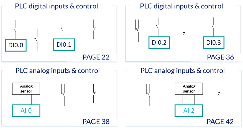
Another example is the representation of the PLC inputs each individually (see Figure 3). In such diagrams, inputs may be drawn separately on several different pages, not necessarily in order. This method is used when the schema is divided into functions and locations – used more in schemas for facilities with multiple devices.
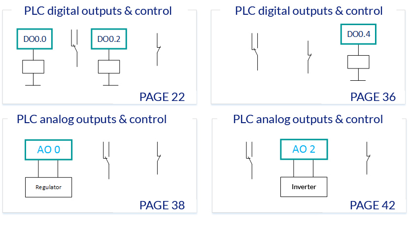
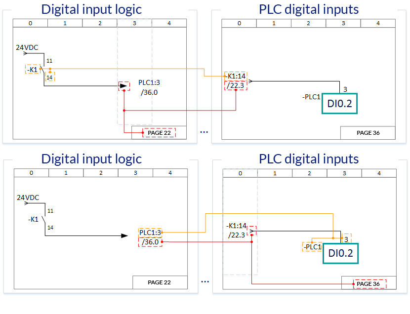
It is very common for the diagrams to show the transition of potential between pages. This also applies to PLC inputs and outputs. In Figure 5, I have included an example where the logic (control) for the digital input is on page 22 and the digital input itself is on page 36. The transition of potential between pages is symbolized by arrows and description.
The description of the potential transition between pages usually includes the device names and the connection number, as well as the page and column on which the potential transitions are placed.
Now I have a request for you to stop for a moment and carefully examine first Figure 5 and then Figure 6. Potential transitions between pages appear in every electrical diagram!
In Figure 6, I have included a hint on how to interpret the notations at the transition of potential between pages. In orange, I have marked the description of the device and its connection to which the potential is connected. I have marked the page and column in red as the location of the potential transition arrows.
PLC outputs
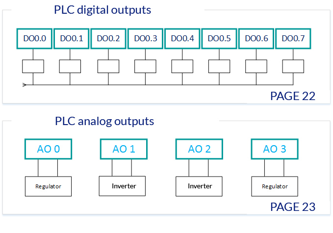
PLC outputs are drawn in the same way as digital inputs. The only difference is that the outputs are drawn in reverse, that is, the output connection is placed at the bottom of the input symbol. The following figures explain that difference: