In this article, I will try to explain how to analyze contact control systems based on ready-made wiring diagrams. In contact electrical systems, relays, contactors and pushbuttons are used to transfer, amplify, multiply, invert or combine control signals into logic functions. By configuring the contact connections, the appropriate behavior of the control system is achieved.
The previous lessons described how the contacts work and the actuators that control these contacts. If you are new to electrical schematics, I recommend that you read the previous lessons first. At the bottom of this article you will find the list of all lessons from the series “How to read electrical and I&C schematic diagrams”.
Download wiring diagram
You will need a sample diagram for the course. On the net I found a diagram of electrical and Control and
Measurement Instruments and Automation of a sewage pumping station. I think enough to start with.
Documentation also includes description and drawings.
#0 Electrical Diagrams – Preliminary Analysis
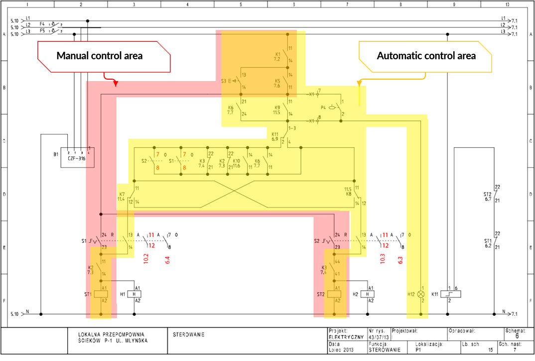
We will be relying on page 6 of the sewage pumping station wiring diagram. Below is a scan of this page with corrections (highlighted in red), as the person drawing this schematic must have overlooked these errors. Such irregularities can happen even in schematics drawn by experienced engineers. Therefore, you should ultimately keep this possibility in mind when analyzing other wiring diagrams.

At first, let’s preliminarily analyze the page. The first 3 lines at the top of the schematic are the 400V power supply (L1, L2, L3). Line L3 was used for control therefore it was protected by overcurrent circuit breaker F5. At the very bottom of the diagram, the line marked N is the neutral potential, so the diagram should be read from top to bottom (according to current flow).
In the diagram of Fig .1. we have seven devices / receivers:
- B1 – CKF-316 Phase Control Sensor (Item 2C).
- ST1 – Contactor to switch on motor M1 of pump P1 (Position 2F).
- H1 – P1 pump operating hours counter (counts up the number of hours the contactor (pump) has been switched on and is displayed on the panel) (Position 3F).
- ST2 – contactor to start motor M2 of pump P2 (Position 7F).
- H2 – P2 pump operating hours counter (Item 7F).
- H12 – Light (working level) on the electrical cabinet door (Position 8F).
- K11 – Bistable relay of “on-off” type – applying voltage to terminal 6 will change state of its auxiliary contacts to opposite (Position 9F ).
All of the elements on page 6 have to do with contactors ST1 and ST2 and we will focus on them. In what follows I will explain what conditions must be met for these contactors to switch on the P1 and P2 pump motors.
#1 Electrical Diagrams – A breakdown of the functions of an electrical diagram
 At first glance, it is not apparent that the control system has been divided into two functions – manual (manual) control and automatic control. If we look at the connections from below, the voltage to the coil of contactor ST1 is divided into two paths on switch S1:
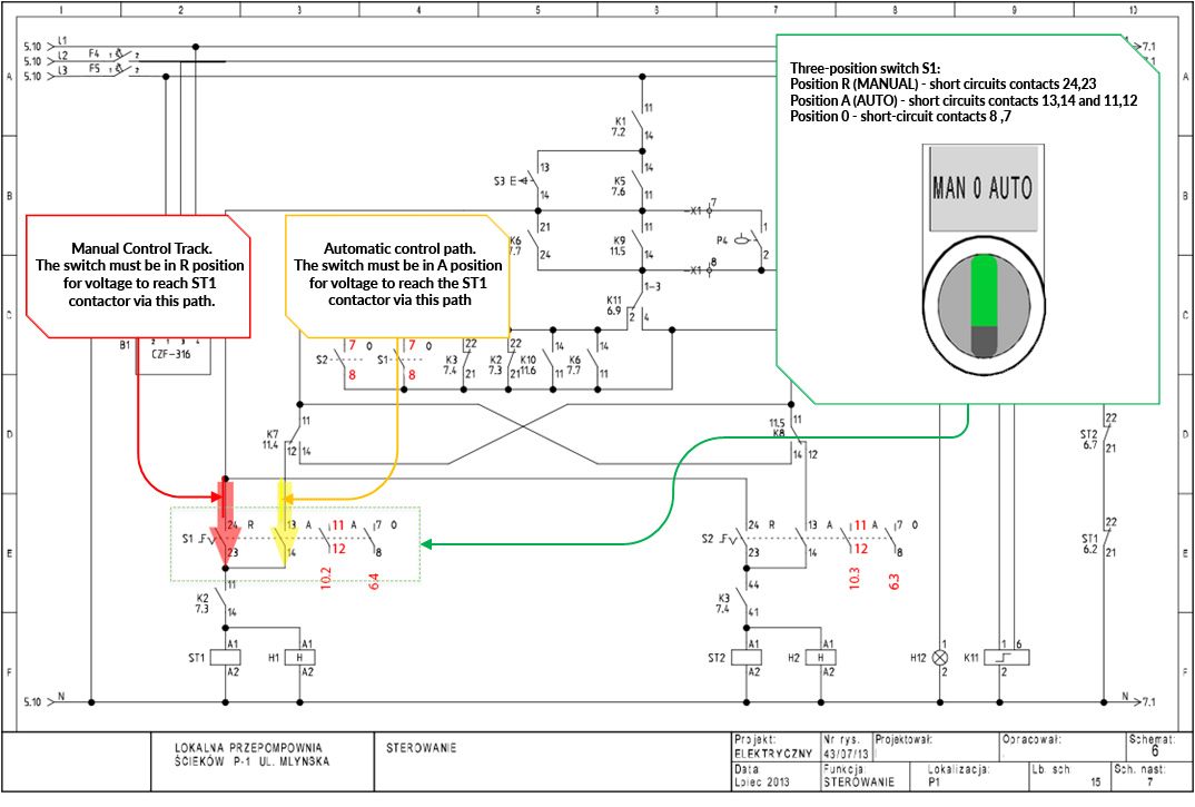
Analogicznie podłączona jest cewka stycznika ST2. Podsumowując powyższe, układ sterowania na tej stronie można podzielić na dwa obszary – sterowanie ręczne i automatyczne.

As you can see from Figure 3, the two control areas overlap in some places. The control circuits are built this way because they share common logic conditions built using contact connections. When designing electrical schematics, the goal is to optimize the number of connections and contacts.
Now that we’ve preliminarily examined this side of the wiring diagram, we can move on to a more thorough examination. Let’s start with the manual control.
#2 Wiring Diagrams – Manual Control
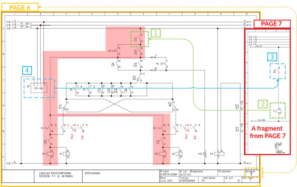
In Figure 4, I have placed page 6 of the diagram with a snippet from page 7 to make it easier for us to analyze the relationships between the diagram pages.
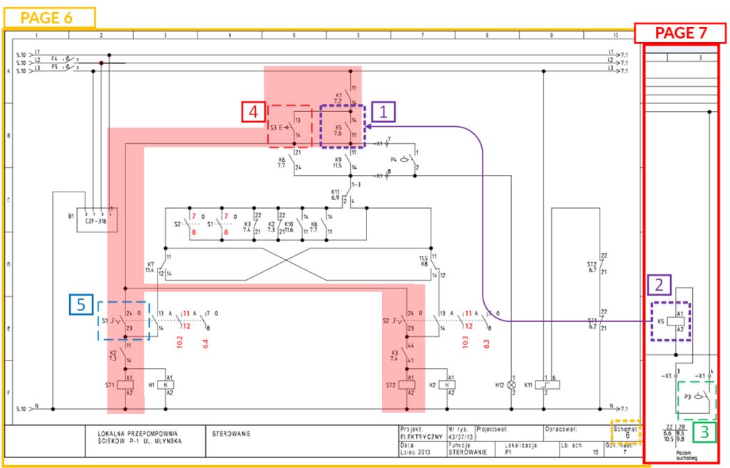
The first contact on the way to switch on contactors ST1 and ST2 in manual mode is the contact of relay K1 [1]. To find out which device will connect the 11,14 contact of the relay K1 [2], follow the “7.2” symbol next to the symbol. The number “7.2” refers to the device that controls the contact. In this case, it is the coil of relay K1 and can be found on page 7 in column 2 [2] .
On page 7, you can see that the device labeled B1 [3] switches on the coil of relay K1 [2]. Next to the designation B1 [3] is reference 6.2 so the device that controls contact B1 (7,8) [3] is on page 6 in column 2 [4].
From page 6 we read that device B1 [4] is a phase monitoring sensor CKF-316. This sensor disconnects contact 7,8 when it detects a loss in at least one phase (L1, L2 or L3) or voltage asymmetry between phases. The purpose of this device is to protect the pump motors from starting with inadequate voltage.
Therefore it can be concluded that the operation of the relay K1 [2] (and its contacts [1]) symbolizes the correctness of the 400V supply. The first condition for switching on the pumps in both manual and automatic control will be correctness of 400V power supply (that is activation of relay K1).
(In a typical sewage pumping station there are 3 floats. 1 – dry float, 2 – pump start float, 3 – overflow alarm float. Dry-running float informs about low sewage level and is designed to turn off sewage pumps. The start float informs about the level suitable to run the pumps. The alarm float informs about high sewage level and switches on the second pump when the first one can’t pump out the sewage (e.g. due to high sewage inflow).
Thus, contact K5 11.14 [1] will close when the waste water has reached this level until the dry float is up.
The button S3 [4] is a service button and is used to force the pumps to run at low effluent level when the dry float P3 is lowered. The S3 button is a bridge on the K5 (parallel connection) on contact K5. Running the water and wastewater pumps dry (no liquid) can damage the pumps!
The next contact on the way to switching on pump P1 is switch S1 [5]. It must be in position R (Manual) for the pump to work in manual mode. Switching the switch to R position will short-circuit contacts S1 23,24.
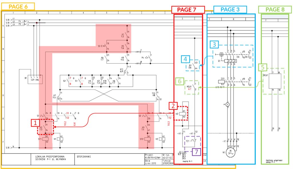
- The motor circuit breaker Q1 [3] will be switched on, so the auxiliary contact Q1 [4] will also be shorted.
- MCU1 [5] “Pump moisture monitoring” does not detect moisture in motor M1 and closes the contact MCU1 [6].
- The TC1 motor thermistor does not detect motor overheating, so the contact TC1 [7] remains closed (when the motor is overheated, contact TC1 opens).
Thus, the failure of relay K2 [2] to energize informs the control system of the failure of pump P1, which includes:
- Q1 – overload of the pump motor P1,
- MCU1 – P1 pump motor flooding (moisture in the motor),
- TC1 – overheating of pump motor P1.
#3 Wiring Diagrams – Manual Control Summary
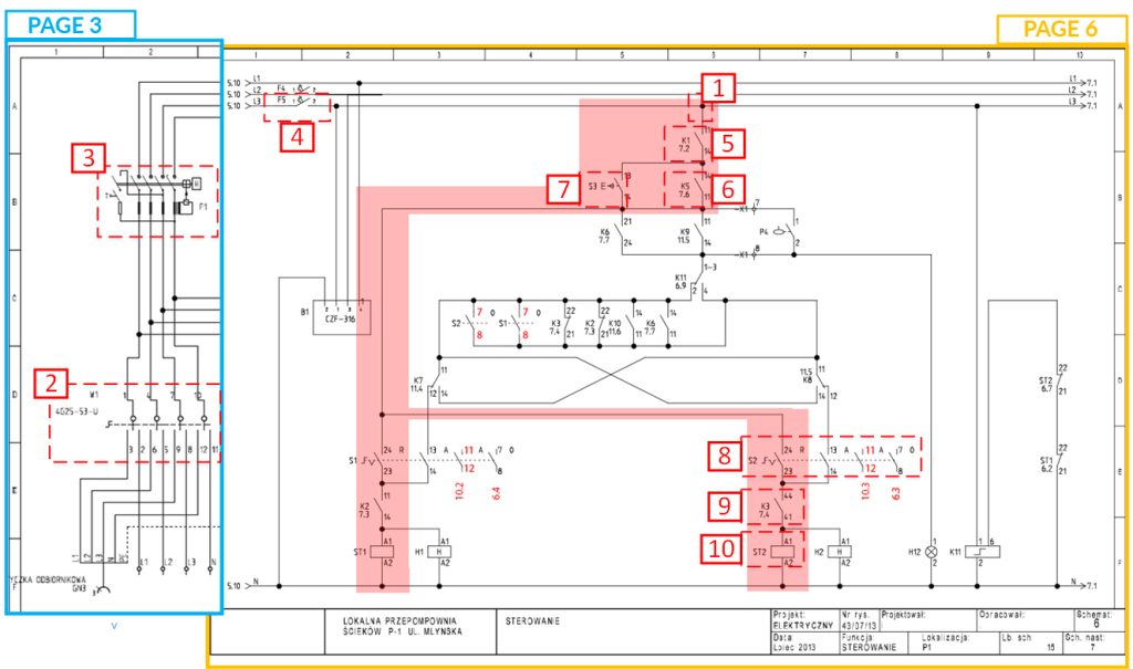
For better contrast, below is a description of the conditions that must be met for pump 2 to turn on, refer to Figure 7:
- [1] supply 230 V to terminal 11 of K1 contact:
- [2] switching on of the main switch W1 (page 3.2),
- [3] F1 differential circuit breaker activation (page 3.2),
- [4] activation of the overcurrent circuit breaker F5 (page 6.1),
- [5] Correctness of 400V power supply (relay K1 switched on),
- [6] Waste water level must be greater than dry running level; dry running float P3 must be up (relay K5 on) or [7] the S3 button is pressed,
- [8] Switch S2 is in R position (manual operation),
- [9] No P2 pump failure detected (K3 relay on),
- [10] If the above conditions are met, the ST2 contactor will start the P2 pump in manual control.
I recommend that you download this diagram and practice on other sites. You will get better with every new schematic. An experienced automation engineer reads schematics like nursery rhymes 🙂