In the previous two lessons, I wrote about relays and contactors, where the electrical contacts were switched electromagnetically. There are many other devices in which the contacts are switched mechanically, inductively, pneumatically or hydraulically. In this lesson, I will provide a summary of contact symbols along with their drives.
We know from previous lesson #2 that electrical contacts can be normally open (NO) and normally closed (NC) or changeover (NCNO). However, shorting or opening the contacts can be controlled in many ways – thanks to actuators. In lessons #2 and #3, electromagnetic drives – coils – have been described. In this article, I will introduce other types of contact control.
Electrical symbols – Contact types
| Symbol | Description |
|---|---|
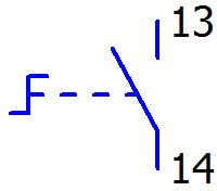
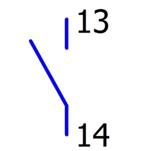 |
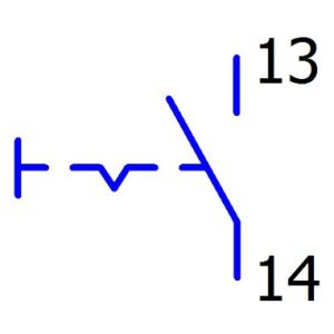
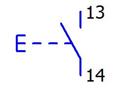
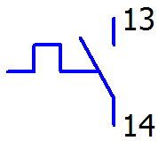
NO contact – general symbol for normally open contact; closing contact. Actuating the actuator (e.g., pushbutton, solenoid) short-circuits the contact and there is a transition between terminals 13 and 14. |
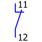 |
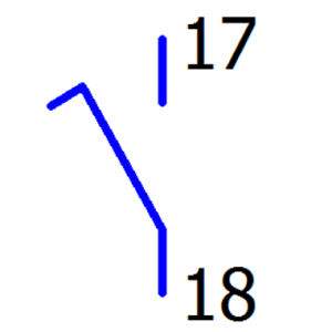
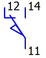
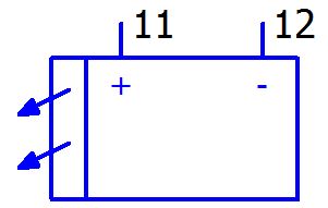
NC contact – general symbol for normally closed contact; opening contact. Activation of the drive opens the contact and there is no transition between terminals 11 and 12 |
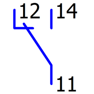 |
NCNO contact – general symbol for a changeover contact; c/o (close/open) contact. Actuating the drive switches the contact from 11.12 to 11.14 |
 |
Contactor main contact – Contactor power contact; Contactor operating contact; |
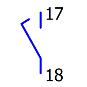 |
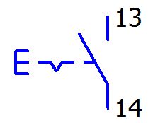
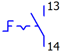
Advance NO contact – This type of contact closes in advance of “normal” contacts connected to the same actuator. It is used in a control system when there is a need to transmit information faster than e.g. switching on the motor by the main contacts. Can be used for protection in control systems. |
 |
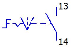
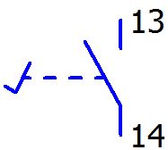
Delay NO contact – This type of contact closes with a delay compared to “normal” contacts connected to the same actuator. It is used in a control system when there is a need to transmit information with a small delay after the main/normal contacts are switched on. It can be used, for example, to confirm motor operation by transmitting a signal via this contact to a lamp or PLC |
There are several other contact symbols on the schematic diagrams, e.g. through-hole, self-reversing and other functional symbols, rather rarely used. When analyzing the wiring diagram, we should first pay attention to the actuator that triggers the contact and analyze its use in the diagram.
Electrical symbols – Contact drives
In wiring diagrams, contact drives can be drawn in several ways. For example, solenoids may be drawn on a different page of the schematic than contacts. This also applies to devices with special functions, e.g. a phase control sensor can be drawn on one page and its auxiliary contact on the next page. Drives with contacts can also be drawn as one symbol, e.g. pressure switch. The wiring diagram will not draw the pipeline in which the pressure switch is installed, only its contact. Therefore, with contacts controlled other than electrically, their drive is drawn. Below is an example on a pressure switch:
| Symbol | Name | Description | Appearance |
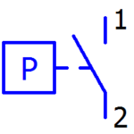 |
Pressure switch; Pressure switch with NO contact The contact is driven by pressure, e.g. air, liquid. | A pressure switch can be called a pressure relay. For example, if the pressure in a pipeline is higher than that set on the pressure switch, the pressure switch contact will be closed. | 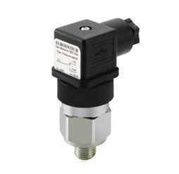 |
Electrical symbols – Mechanical drives
Mechanical drives are those that are controlled manually by man (eg, buttons, switches) or as a result of the action of some mechanical element (switches, cams) . What is a button probably everyone knows. Buttons can be found almost everywhere, in the elevator, on the keyboard, on the TV remote control – they are monostable buttons. Buttons, or rather switches, such as in some cars, for example, from the emergency lights, fog lamps – these are bistable buttons, which remain in the pressed position after triggering and return to the original position after re-pressing – the same with turning. In automation, monostable buttons are used for simple control functions such as start, stop, reset, or e.g. protection – limit switches.
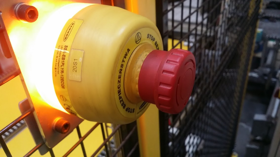
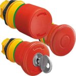 Almost every machine has safety buttons, which are almost always interlocked. Interlocking means that the button will be locked after pressed. Unlocking such a button is only possible after turning the button or pulling hard, or even only after turning a key. Safety buttons are used to disconnect the control circuit and are intended to bring the machine to a stop as quickly as possible. This is one of the reasons why NC contacts are always used for safety buttons – pressing such a button opens the circuit.
In the following table, the electrical symbols of the actuators are mainly drawn with NO contacts, because the actuator for NC and c/o changeover contacts will look identical, only the contact type differs.
Electrical Symbols – Manually Operated Contacts:
| Symbol | Name | Description | Sample Appearance |
|---|---|---|---|
 |
NO generic button; monostable button. | General button used for controlled on, off, acknowledge, etc. | 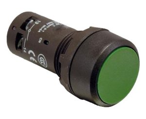 |
 |
NO generic button; bistable | NO two-position bistable switch. It opens in the normal position and closes when turned/pressed. | 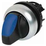 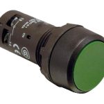 |
 |
NO pushbutton; monostable pushbutton. | General button used for controlled on, off, acknowledge, etc. | |
 |
NO pushbutton switch; bistable pushbutton. | It may look the same as a regular button, but its operation is different. When pressed, it remains in the pressed position. | |
 |
NO switch, controlled by turning, 3 switching positions | Such a 3-position switch usually has a minimum of 2 NO or NC contact fields – one each for positions 1 and 2. Position 0 – off. Used in control systems to switch on a function, e.g. automatic or manual control and 0 – off. | 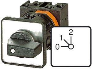 |
 |
NO switch, twist-operated, monostable | This is the symbol for the self-return switch, when turned the mechanism will automatically return to position 0. | 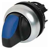 |
 |
NO switch, twist-operated, bistable |
This is the symbol for a non-return switch, the switch may look identical to the example above. | |
 |
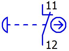
NO button controlled by pedal; | Buttons in the form of pedals are used e.g. on machines where the operator’s hands are busy and he needs to activate some option, e.g. a momentary stop of the conveyor. | 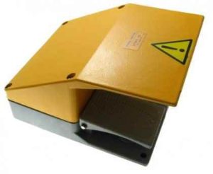 |
 |
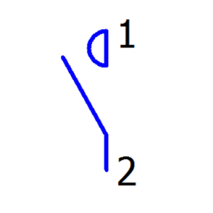
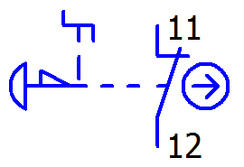
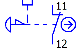
Emergency pushbutton, pushbutton type, monostable, non-latching, with NC contact | Generic symbol for a safety button. Used with special safety modules. | 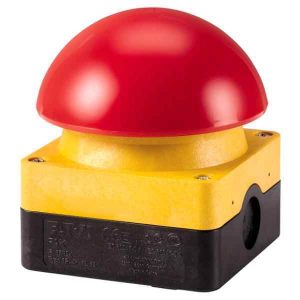 |
 |
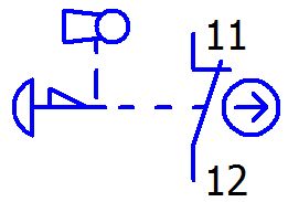
Safety pushbutton locking, with turn-to-reset, with NC contact | When the button is pressed, the circuit is disconnected. The button will not be released until manually turned. | 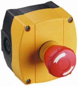 |
 |
Emergency push button with latching catch, released by pulling, with NC contact | When the button is pressed, the circuit is disconnected. The button will not be released until it is manually pulled back. | 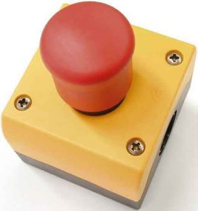 |
 |
Emergency pushbutton interlocked with key release, with NC contact | Such buttons are used in places where releasing the button can be done only by a person holding a key, e.g. after investigating the reason of machine stoppage. | 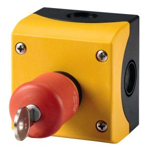 |
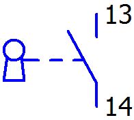 |
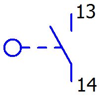
NO contact controlled by key; ignition monostable | Keypads are used for special functions such as authorization of operation, resetting or acknowledgement of alarm, resetting the counter. | 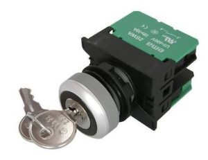 |
 |
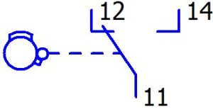
NO contact controlled by roller; roller limit switch | Limiters are used to provide information about the end position of an item. Turning the roller will short out the contact. Industrial limit switches usually have two contacts, NO and NC. | 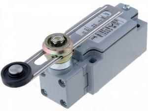 |
 |
Limit controlled change-over contact; Limit switch | This is the generic symbol for limit switches. Limiters can have very many configurations and different rollers. | 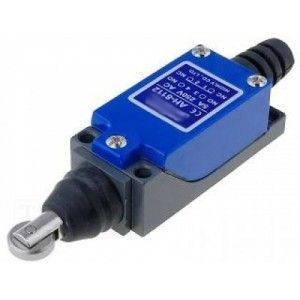 |
 |
A changeover contact controlled by the cam end position. | Such contacts can be found, for example, in throttles where the rotation of the throttle turns the cam. End positions of open and closed press the roller and the contact switches. | 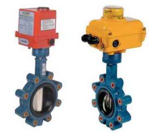 |
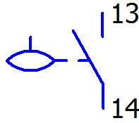 |
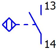
NO contact controlled by float; Float | Floats are used to control the level in tanks. I.e. A float can be used to detect tank overflow when the tank is full. | 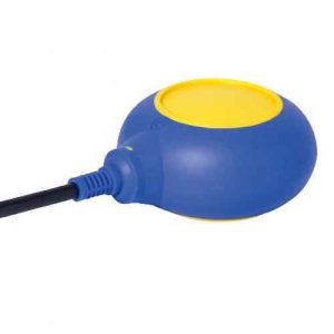 |
Electrical symbols – Sensory actuators
Sensory drives are those that capture a signal from their surrounding environment. Typically, such sensors contain electronics. Such drives include, inductive sensors, optical sensors, acoustic magnetic sensors, etc.
Electrical sensor symbols:
| Symbol | Name | Description | Sample Appearance |
 |
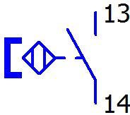
NO contact with proximity actuator. I.e. induction sensor | The inductive sensor closes the NO contact when metal is brought close to it. | 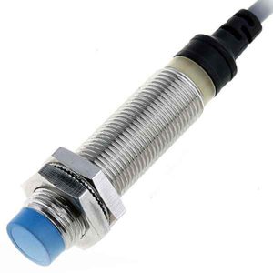 |
 |
NO contact with proximity actuator via magnet; reed switch | Reed switches are used to control the opening of e.g. an electrical cabinet, door, manhole, barrier etc. | 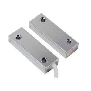 |
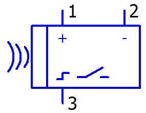 |
Ultrasonic sensor. PNP | An ultrasonic sensor is used to detect objects. The sensor emits an acoustic signal and picks up waves reflected from the obstacle. | 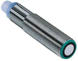 |
|
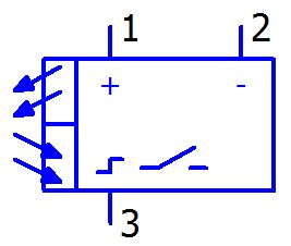
Light barrier; optical transmitter and receiver with NO (PNP) contact; | They are used for object detection, zone security, etc. | 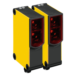 |
 |
Reflective optical sensor with NO contact (PNP). | Opical sensor is used for object detection, zone security, etc. | 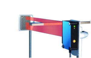 |
 |
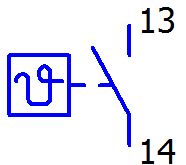
Normally-open (NO) contact with self-actuating thermal actuation | This is a generic symbol for thermally triggered protections. i.e. Motor circuit breaker, overcurrent | 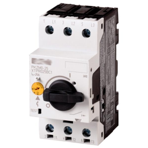 |
 |
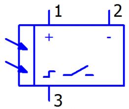
Temperature-controlled NO contact; temperature switch; thermostat | Contact triggered when given temperature is exceeded | 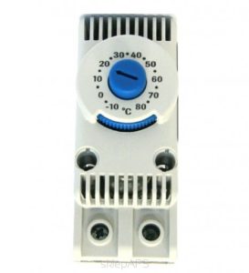 |
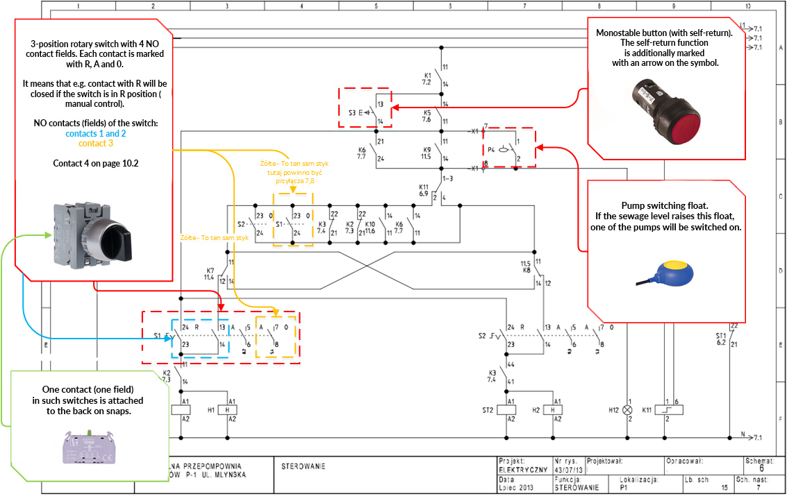
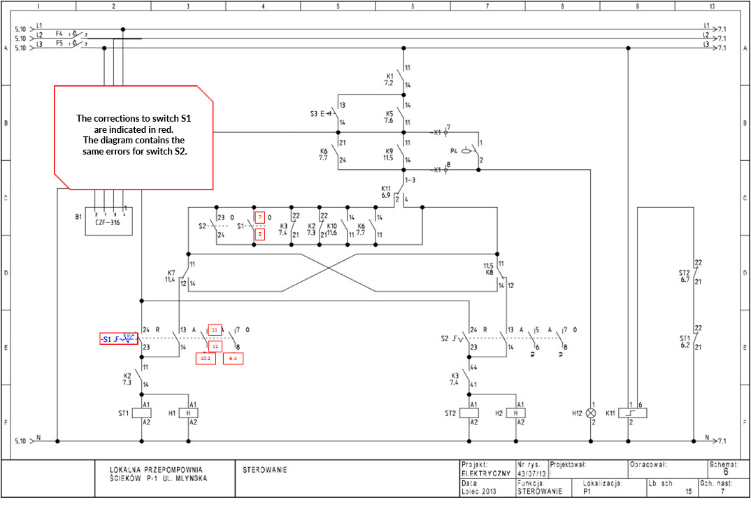
Electrical symbols – Contacts in the electrical diagram for wastewater pumping stations
There are a few errors in our sample wiring diagram. Among other things, on the designation of switch contacts S1 and S2 – R0A (Manual control / Off / Automatic control). According to the equipment list (page 25 according to PDF) these are knob switches SP22-P3-10. On slide 2, I have included corrections to the S1 switch.