Contactor – an electrical mechanism switch, adjustable other than manual way, with only one resting position of movable contacts, capable of switching on, switching off, and conducting current under normal circuit conditions, as well as under overloads.
Assume I don’t know what a contactor is. I read the above definition and…I still don’t know. To begin with, I will try to explain to you what a contactor is – as simple as that. Next, we will go over its symbology and the markings of this device in the schematics.
Electrical Symbols – What is a contactor?
In the previous lesson, electromagnetic relays were described in quite some detail. An electromagnetic contactor can be compared to a relay because the principle of operation is very similar: when the coil of the contactor is energized, the main contacts of the contactor close (short-circuit). The main difference between a relay and a contactor is that contactors are used to switch main circuits (e.g. motors), while relays are designed to connect auxiliary circuits (e.g. signaling, control).
The following animation shows the contactor when it is switched on. When the coil (yellow) is energized, the main contact closes (red) and current flows from the source to the load (e.g., motor):
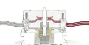
Thus, we can say that a contactor is a switch whose operating contacts are closed by means of an electromagnet (coil) and kept in that state as long as the coil voltage is high enough. When the solenoid coil circuit is broken, the jumper falls (under the action of a spring) and the operating contacts open.
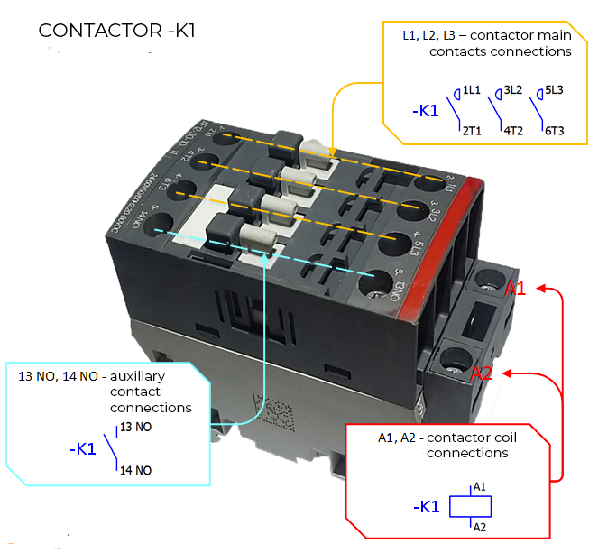
In simple terms, a contactor consists of a coil, working (main) contacts and additional/auxiliary contacts.
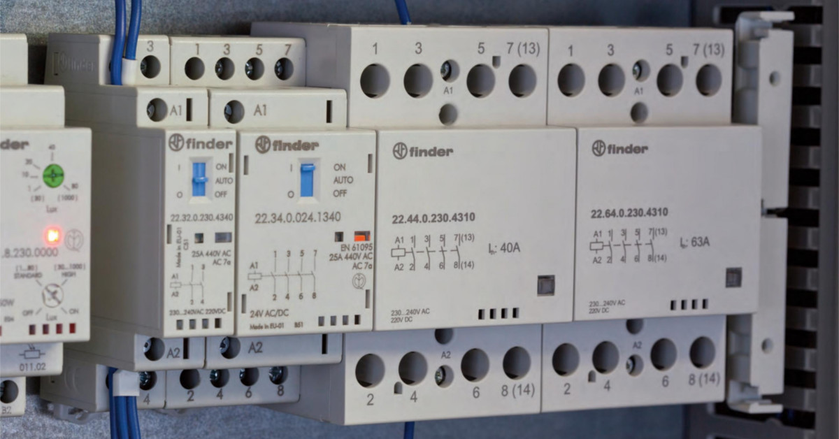
Coil – characterized by its supply voltage. To “start, trigger” an electric coil, you must supply it with either DC or AC power depending on the type of coil. The contactor coil can come in different variants depending on the supply voltage:
- 12 VDC , 12 VAC,
- 24 VDC, 24 VAC,
- 48 VDC
- 110 VAC
- 230 VAC.
Working contacts – these are the main contacts of the contactor, usually three because of 3-phase receivers; normally-open. In relation to auxiliary contacts or relay contacts, the main contacts are used to start the power receivers (e.g. motors, fans, heaters).
Auxiliary contacts – have the same role as the relay contacts. They are used to communicate information. They can be NO or NC contacts. They engage (NO) or disengage (NC) together with the main contacts as soon as the coil is energized. The auxiliary contacts of the contactor are used for:
- to transmit information about the operation of the receiver, e.g. to a PLC or by lighting a signal lamp,
- blocking the activation of another contactor,
- self-sustaining of the contactor,
- Contactor control logic, such as cascade control,
Electrical Symbols – Relay vs Contactor
The following table summarizes the differences between a contactor and a relay:
| CONTACTOR | RELAY |
|---|---|
| DIFFERENCES | |
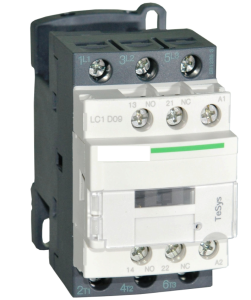
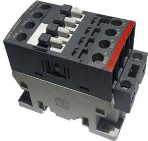
Fig. 3 3-phase contactor |
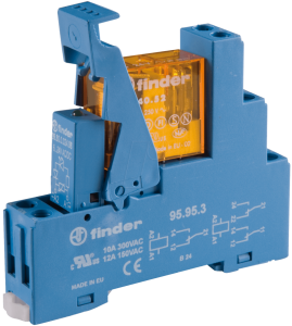
Electromagnetic relay, 2 pole |
| A device for switching strong current systems. Contactors are used for switching electrical devices such as motors, heaters, transformers, etc. | Devices that switch/transmit low current or zero potential signals. Relays are used, for example, to transmit a signal to a PLC, turn on a signal, etc. |
| Larger sizes due to their purpose | Smaller sizes. |
| Higher current-carrying capacity of the main contacts of the contactor. Auxiliary contacts (with the same function as the relay contacts) usually have a lower load capacity. | Lower current carrying capacity of relay contacts. The operating current of relay contacts usually ranges from 0.5 to 10A. |
| Relatively lower switching life. | Increased switching durability. |
| COMMON FEATURES | |
|
|
Electrical Symbols – Contactor Construction and Contactor Symbol
The contactor symbol consists of three parts: coil, main contacts and auxiliary contacts.
- There can only be one coil in a contactor.
- The main contacts of a contactor are three and are always drawn as one symbol in the form of three contacts.
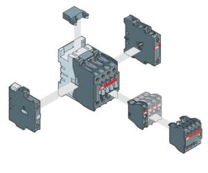
- The auxiliary contacts, as a symbol, are used in the same way as the relay contacts. There may be several depending on the contactor and the modules being attached. They can be drawn not necessarily on the same side as the coil or main contacts of the contactor.
| SYMBOL | DESCRIPTION |
|---|---|
 |
Contactor coil |
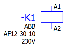 |
Contactor coil with description. On the left side of the coil is placed its unique ID name, in this case -K1. There cannot be more than one coil of a given contactor on a schematic, thus there cannot be two coils with the same ID. Under the ID on some schematics you will find a description to help identify the device e.g. company, model, function, coil voltage |
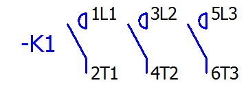 |
Contactor main contacts symbol. Main contacts are always drawn together. |
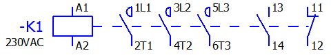 |
Symbols for the entire contactor. Coil, main contacts and two auxiliary contacts NO and NC. If such a symbol is drawn on a single line then the ID (-K1) can only be assigned to the coil. On most diagrams, a dashed line is drawn from the coil to the last contact. |
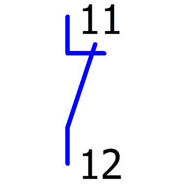 |
NC auxiliary contact, normally closed, may have different connector designations, e.g. 51 and 52, 61 and 62 |
 |
NO auxiliary contact, normally open, may have different connector designations, e.g. 23 and 24, 33 and 34 |
Electrical Symbols – How to read electrical schematics
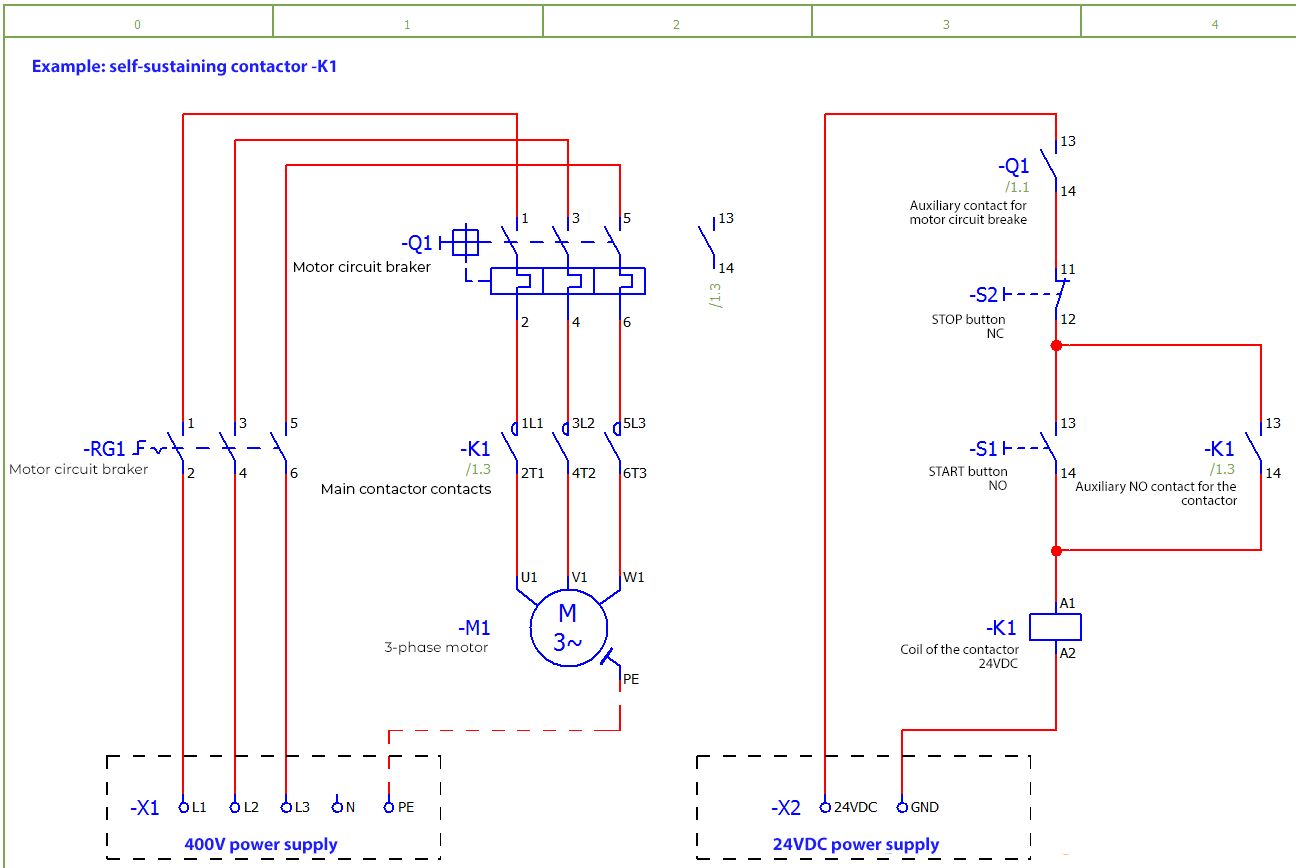
To explain the operation of the contactor, I have prepared a diagram (Fig. 5.) with the option of self-sustained motor operation. Thanks to the parallel connection of the START button and the additional NO contact of the contactor, it is possible to keep the motor running after releasing the START button.
Components:
- RG1 – main circuit breaker
- Q1 – motor circuit breaker,
- K1 – contactor with auxiliary contact
- M1 – three-phase motor
- S2 – NC button
- S1 – NO button
- X1,X2 – connectors
Let’s examine the control system in Figure 5 one by one:
- For the motor to start we have to switch on the main switch –RG1, the motor circuit breaker –Q1, and the contactor coil –K1.
- If you turn on the –Q1 motor circuit breaker, then in the 24VDC control circuit, the –Q1(13,14) contact will close.
- The STOP-S2 button is NC – normally closed, so it conducts current when not pressed.
- Pressing the START –S1 button will switch on the coil of the contactor –K1. The coil will switch on the main contacts and close the additional NO contact of the contactor K1 (13,14).
- When releasing the START button –S1, the contactor coil will continue to be energized by the additional contacts of the contactor –K1. This means that the motor started after the START button was pressed once and is still running.
- We will only switch off the contactor –K1 by breaking the circuit with the STOP button –S2 or after overloading the motor and tripping the breaker –Q1 (its additional contact –Q1 13,14 will disconnect after overloading).
Additional findings from Figure 5:
- Additional unconnected symbols may appear in the schematics next to the main devices (e.g., coils, motor circuit breakers). Fig. 5 shows that an unconnected NO contact 13,14 appears next to the symbol of the motor circuit breaker -Q1. This is such a table of contents of additional contacts of the device, under this contact there is a reference to its item 1.3 (page 1 column 3). This is very useful when the motor circuit breaker is on given page and its auxiliary contact is, for example, a few pages down.
- Analyze how the circuit would work if we took away the extra contactor contact -K1 (13,14). When you press START -S1 the engine would start but releasing the button causes the motor to stop immediately.
- Note that the motor is powered by 400V and this is the voltage on the main contacts of the contactor while the coil -K1 is powered by 24VDC.
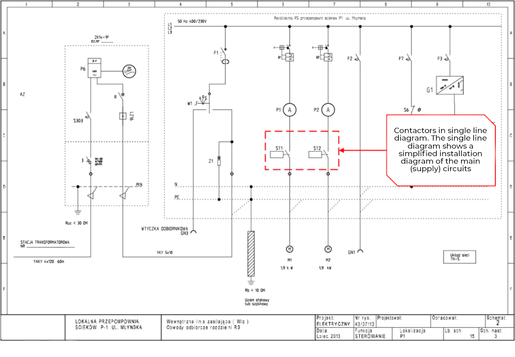
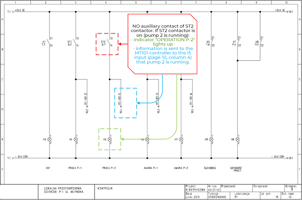
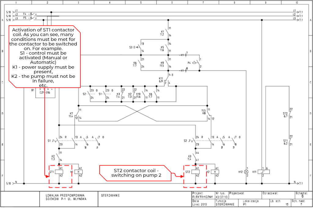
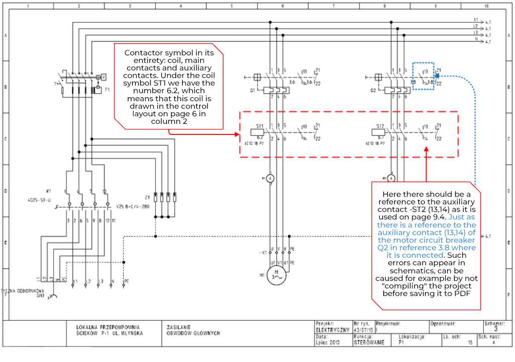
Electrical symbols – Contacts in the ready made diagram for wastewater pumping stations
In the sample pumping station schematic, there are two high-current loads – wastewater pumps, so there are two contactors. Each motor must be protected against overload, so there is a motor circuit breaker before the main contactor contacts. The auxiliary contact of the contactor was used to light the lamp and to transmit the signal to the MT101 controller. I have included comments on these contactors in the slides below: