A plant diagram is undoubtedly one of the most important documents in a manufacturing plant. We’ll start our schematic reading course with the simplest item we can find in an electrical closet – the cable connector (ZUG). Connectors are a very important element in almost every electrical installation and control and measurement equipment. They provide installation safety and connection security.
Manufacturers of cable connectors have already reached such a level that it is possible to adapt various models, even to the most demanding installations. In the offers from manufacturers we can find connectors with different purpose, functionality and current load. Connectors are mainly divided by connection mechanism, such as screw connectors, spring connectors, self-locking connectors.
Download wiring diagram
You will need a sample diagram for the course. On the net I found a diagram of electrical and Control and
Measurement Instruments and Automation of a sewage pumping station. I think enough to start with.
Documentation also includes description and drawings.
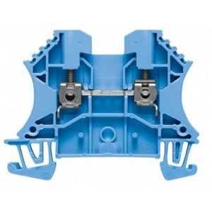
Electrical Diagrams – What is a connector and otherwise a zug or terminal:
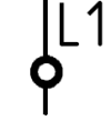
Next to the connector symbol is its designation – in this case L1. There are many connectors and terminal strips in the schematic. Below is a summary of the connector symbol, its appearance and placement on the schematic. The symbol for the connector is a small circle that is placed on the line of the cable connection that the connector connects.
| SYMBOL | SYMBOL DESCRIPTION | VIEW | ELECTRICAL WIRING DIAGRAM |
 |
Nipple, clamp, split connection | 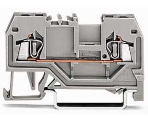 |
|
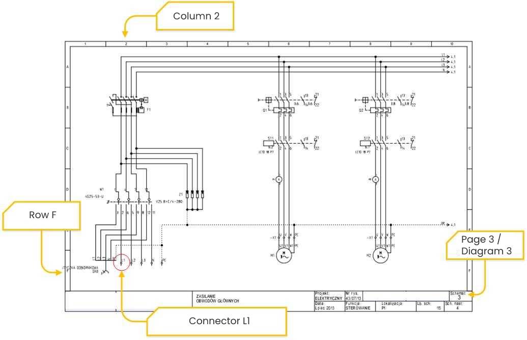
The connector I chose for the example is used to connect the first phase in a three-phase power system. The following parameters can be assigned to it:
- The connector symbol in the diagram is found on page 3 in column 2 and row F,
- On page 13, column 1 and row B, you can specify where the connector was placed in the electrical cabinet,
- The connector is assigned to terminal strip X1 to the “POWER” section,
- On page 27 (according to the PDF) of the “Terminal List,” you will find that the X1:L1 connector has the code ZUG-G10

ATTENTION! The connector symbol should not be confused with the connection symbol shown below:
Wiring diagrams – Connections in the wiring diagram – black dots
| SYMBOL | SYMBOL DESCRIPTION | VIEW | ELECTRICAL WIRING DIAGRAM |
• |
Wire connection |
For example:
|
e.g. page 3 entry 4 E
|
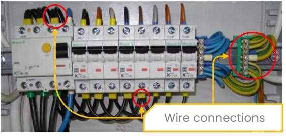

Connections in electrical and control systems are not just made with connectors. The wire ends can also be connected to the terminals of other devices.
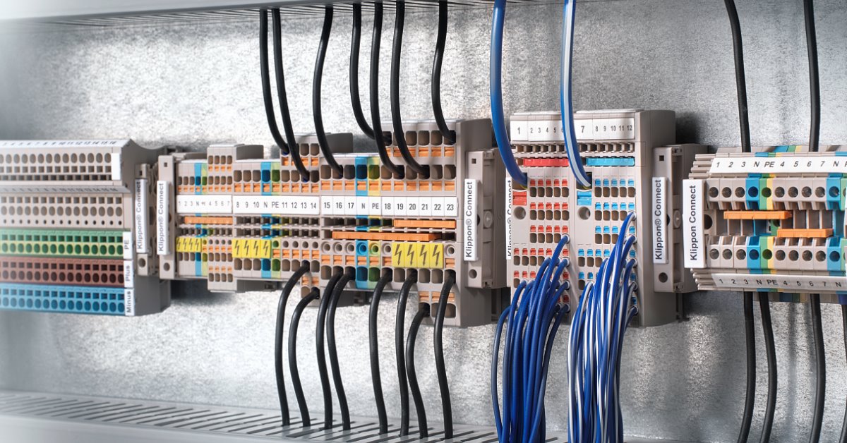
Electrical diagrams – What is a terminal strip
A single connector is used to extend a cable connection. By mounting the connectors one next to the other on the rails, you get terminal strips that are used to organize the connections in electrical cabinets. Terminal strips in simple installations are marked with X1, X2, X3, X4. In more complex electrical cabinets, strips are divided and labeled for example by function.
For example, if 20 analog sensors and 20 digital signals are connected to an electrical cabinet, 2 terminal strips (e.g. AN1 and DI1) can be installed for better organization. If we would like to go further, analog signals can be divided into further strips, e.g:
- ANT0.1 strip for temperature sensors on boilers,
- ANT0.2 strip for temperature sensors on pipelines,
- ANP1 strip for pressure sensors,
- ANL1 strip for level sensors,
- etc. etc.
Although in practice you will most often encounter strips and connectors with the letter X.
| SYMBOL | SYMBOL DESCRIPTION | VIEW | ELECTRICAL WIRING DIAGRAM |
|
|
Terminal strip |
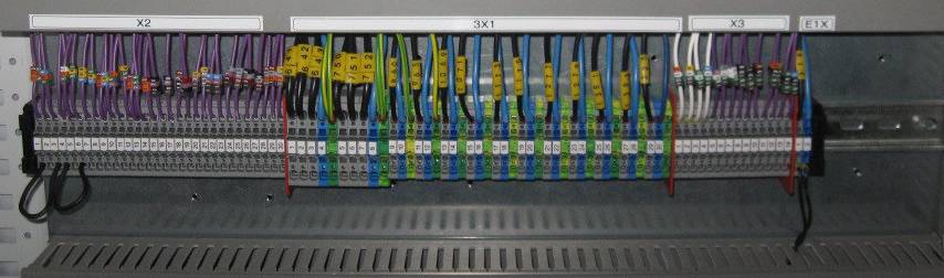
For example, the image shows 4 terminal strips: X2, 3X1, X3 and EX1
|
e.g. page 3 entry 4 E
|

Note that in the schematics, terminal strips are marked in one place on the left (X1). If the subsequent electrical terminals are placed in a single horizontal line, the strip designation may not be added to the subsequent terminals. It is not necessary for the terminal strip to be drawn in only one place on the diagram. For organization and readability of the diagram, a given strip can be drawn on several pages, not necessarily in order.
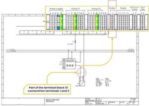
Wiring diagrams – Connection to the electrical cabinet for power and external devices
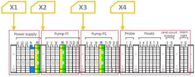
In the example diagram of the wastewater pumping station, one X1 terminal strip is used to connect all devices. In small control and measurement cabinets this is not a big problem, but in larger installations such solutions are unacceptable. Personally, I would divide the X1 terminal strip into 4, at least because the electrical terminals for connecting the pumps have identical designations:
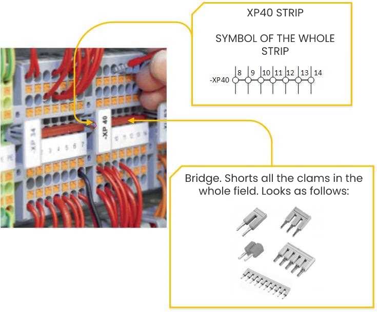
Wiring diagrams – Potential separation on terminal strip
Connectors can be used for potential separation. For example, if you want to make a strip with seven terminals and all of them have the same potential, e.g. 24VDC, you can use specially designed bridges. It would look like this: