During designing control systems, we often enter an area quite specific in its essence – safety. A topic known by many, underestimated by many, and finally – misunderstood by many. It’s not that no one understands what sefety is. During designing something, everyone is responsible (or at least they should feel responsible) for giving the customer an efficient device that performs its function, but at the same time safe – protected against possible faults of the control system and operating errors at a sufficiently high level, adequate to the level of threats that they will lurk during operation.
Safety level assessment
Often, however, we are not sure whether the security we use will prove itself in practice and whether it complies with the principles of art. However, can it be reliably assessed? Are there any methods to check the degree of protection we have proposed in our system and is this level adequate to the risk? Roughly the answer is yes, it is possible. Today’s safety standards allow to assess this level of security not only qualitatively (appropriate combination of devices, e.g. redundancy), but also quantitatively (use of appropriate devices with appropriate parameters). This does not mean that it is enough to take the first device with great parameters – it also needs to be adjusted, if only because of the environmental conditions in which this device is to work. Additionally, functional limitations of these devices should be taken into account, which may only manifest themselves at specific moments. The whole range of diversity makes the subject of safety not an easy topic. And although each major manufacturer of safety systems offers a variety of guides in which we can find proven safety systems, without going a bit deeper into the essence of the matter, we can navigate this topic a bit in the dark – especially if the diagram needs to be slightly adapted to our safety function. How can we be sure that an apparently small change will not contribute a significant factor to the safety function? Without in-depth understanding, we can only guess.
SERIES OF ARTICLES ABOUT SAFETY
With this article I would like to start a shorter (or longer – it all depends on your reception) series of articles on the design of safety systems in accordance with the rules of art. However, I would not like to be considered alpha and omega on this topic – I am not going to discover any amazing security features of my own here. A few years ago, being a total beginner in this topic, I started looking for reliable information on this topic. And we found them – probably in the manuals of the institution that has the greatest influence on the content of the standards related to machine safety, namely IFA (this name is present – previously it was known as BIA, BGIA, etc.). You can read about IFA, for example, here:
Knowledgeable readers probably know the guides published by the Institute. And it can certainly be said that they very extensively present the security problem in accordance with the applicable, commonly used security standards, including PN-EN 13 849-1. The institute is also constantly developing a widely available software called SISTEMA, which facilitates the design of safety functions without going into the complex mathematical formulas associated with the parameters of safety devices. The program can be downloaded for free after prior registration from the website:
And based on such a solid basis – interesting examples provided by IFA in its guides and the use of the SISTEMA program – I would like to show you, at least partially, that correct, clear as to the safety functions performed, the design of safety systems is possible (although often not easy – especially on the beginning of our learning). I would like to point out that the series of guides is not intended to discuss in detail the Machinery Directive, applicable national regulations, risk analysis methods, etc. Nevertheless, basic knowledge in this field is at least desirable, so in the links below I present the most important materials, compulsory for everyone who wants to deal with safety issues properly. You do not need to memorize all the details – they will come to your mind anyway after some practical use of them 😉
The series of articles will serve as an aid to explain (for those who have problems understanding) the technical procedure for selecting the correct protective measures for specific safety functions. I clearly point out that this is only one of several stages of the correct design of safe machines, but not the only one. For designers of control systems, however, it is necessary, it is not necessary to make anyone aware that we (designers, but also, for example, UR) also bear a certain responsibility for the safe operation of the entire machine.
I encourage you to read the following guides (at least briefly) for those who are completely not in the topic. On the basis of certain information from them, certain design activities will be translated, and relatively short articles cannot be written about everything, because it will be easy to get lost in it all and nothing will come out of our learning. I will also try to recall (present) some key information relevant to a specific example, so as to some degree systematize the learned knowledge.
Where to start when implementing safety systems?
If you have read the above materials and do not feel completely unfamiliar, I invite you to arrange your first safety function (SF – Safety Function, we will use this abbreviation in further analyzes).
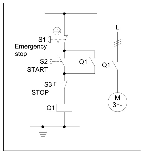
As the first and simplest safety function, on the basis of which we will also get acquainted with the SISTEMA software, let it be the STO function (Safe Torque OFF) for the classic contactor system controlling the operation of the electric motor.
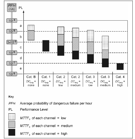
To begin with, let’s specify what the STO function is characterized by. Here is a chart (taken from IFA Report 7 / 2013e – link above) with an explanation:
As can be seen normally, in order for the drive to work, the STO element / subsystem must be active (it can be the drive contactor, pulse enable in the frequency converter, etc.). When this signal is taken, the drive stops uncontrolled without any deceleration ramps (coasting). Of course, this type of alloy is not appropriate for every application.
Without any connection with the manufacturer or any distributor, I will use the example of EATON components, how you can quickly create (without going into too much detail) and assess such a safety function.
The diagram this time comes from the publication BGIA Report 2/2008, to which you also have a link above:
Design of safety functions
I assume that we already have SISTEMA software installed in the latest available version. The next step, which will make our work much easier, will be to download libraries of elements that already have assigned safety-related parameter values (in this case, we mainly mean MTTFd and B10d – the meaning of these parameters can be found in the above-mentioned publications). On the slogan “EATON SISTEMA LIBRARY” in Google, the following link appears: Functional Safety
After entering it, we see the possibility of downloading libraries to the appropriate version of our SISTEM:
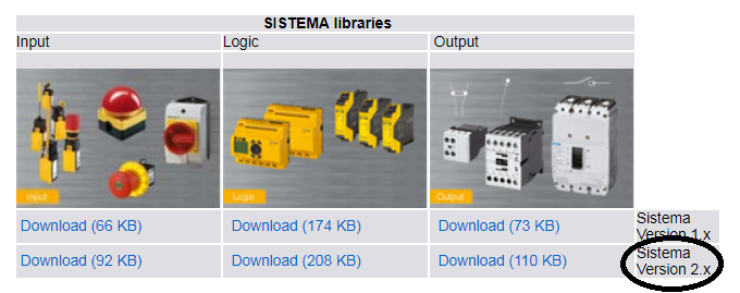
As the latest available version (and this is what the article refers to) is version 2.x, we download it and save anywhere on the library disk for each of the subsystems – input, logic, output. After downloading, unpack these libraries to any folder.
The next step is to start the SISTEMA program. At the first launch, the start screen is displayed in which we can configure our folders, language, etc. The only thing I changed was the language to English, the other settings remained unchanged. These settings can always be changed in the Edit / Sistema Configurator menu.
After launching, we create a new project which will include individual safety functions (in our case one – STO). By clicking New… in the toolbar, we are creating a new project that we can name, comment on, add relevant documents, if any. We also see the Safety functions tab where we will declare our safety function.
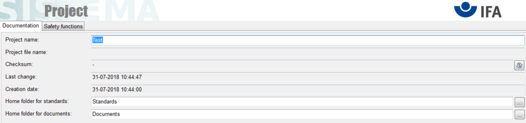
We go to this tab, select New… and double-click our created SF (Safety Function).
In the newly opened window, declare the name of this function, we can accurately comment on how it should work, add additional documents related to this function (e.g. fragment of the diagram). I called this function briefly – STO.
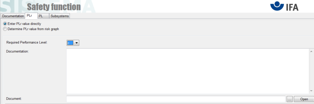
The next step (and another tab) is to define the required security level (PLr – required). We can define this degree directly in the program using a graph or having already calculated one – just enter it.
Let us assume that we already know the desired PL and it amounts the PLc …
In the Subsystems tab, we define the subsystems that are part of our SF. Click on this tab New…, define the name and some important things.
In the PL tab:
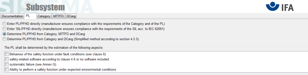
it is necessary to “tag” all options (we leave the default determination of the PL / PHFd level based on Category, MTTFD and DCavg. What do these fields mean for “tag”? The content itself tells us something – that the software used meets the safety conditions (or there is no software at all), the subsystem is immune to systematic errors, etc. Answers to these questions can be found in the aforementioned publication BGIA Report 2/2008, perhaps in the next articles it will be necessary to elaborate on this topic further.
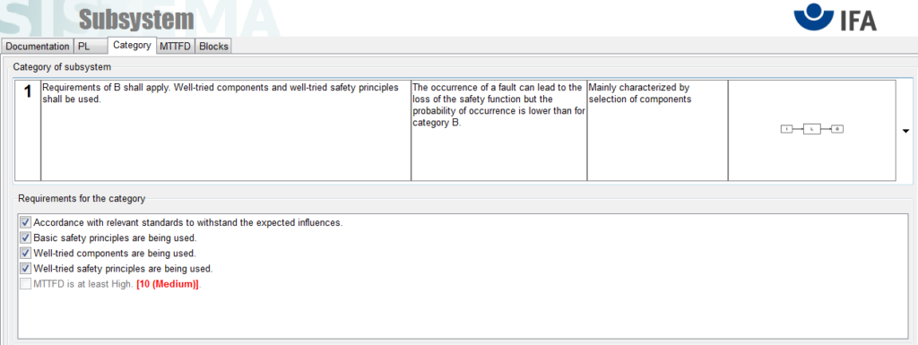
On the next Category tab, define the Category in which our subsystem will operate. Our simple SF (looking at possible variants to choose from) matches category B or 1. The higher the Category, the more secure our SF is. The main difference between these categories is the use of proven safety features and safety rules. In our case, the E-stop button and the contactor are proven safety elements, so we can safely choose Category 1. Proven safety rules include, for example, oversizing of contactors, grounding one pole of the control circuit, use of protection elements (fuses) in the control circuit, the principle of “closed” circuit current ”, ie in the event of a voltage failure, the system will go into a safe state (in our case, the dangerous motor movement will be stopped). More detailed information in the literature provided above.
After selecting the category to be used, we click the options that appear in the window.
In the MTTFd tab, we can define the so-called Mission Time for which the entire system is designed (standard time is 20 years – 20 a).
Finally, the last tab is Blocks, in which we will add individual blocks.
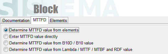
By default, we select the New… option in it, we give a name to a new block, eg E-stop, we can, for example, add a catalog card regarding the device. On the MTTFd tab, in turn, we can specify the mentioned parameter using various options. We will intentionally use the downloaded libraries for EATON, so we will choose the option:
and a new Elements tab will appear.
In this tab, this time we will choose the Library option instead of New… In the new window, we need to add the libraries that we unpacked earlier (Add Local Library option), and then go to the list of elements:
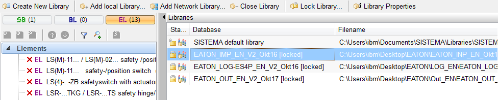
in the library for input devices.
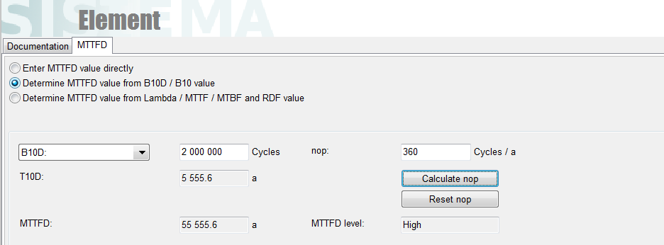
On the list, find our e-stop (M-22 e-stop PVT Types) and click Load & Close. We delete the unknown element that is automatically created when adding a new block, so that only our e-stop remains. Now, by double clicking on our e-stop, we can configure it a bit. In fact, the only information we need to determine (we assume MTTFd calculation based on B10d) is the number of operations performed during the year. We can either enter it manually or use Calculate nop and specify the appropriate parameters. We will define a single use of the e-stop button during each day of the year, i.e. enter 360 and confirm with ENTER. On this basis, the parameters MTTFd and T10d will be calculated.
If everything is OK so far, we should have a similar view on the left side of the project window:
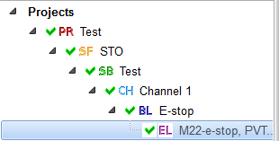
The most important are the green ticks which mean that the necessary conditions (for certain assumptions) have been met so far.
From the safety elements of our function, we still have a contactor to add. So, in the project window, click on the SB field (in my case, additionally marked as Test) and, just like we added e-stop, now add our contactor as a separate block (DILM 12 element in the output library). We assume, for example, switching on the contactor twice a day for 365 days, which gives us 730 operations a year.
The project screen should look like this:
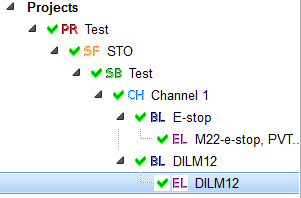
In fact, this is the end of designing our safety function. You can see that by exceeding, for example, the number of contactor usage cycles above a certain value, an alarm for exceeding the T10d parameter value will appear and our SF will no longer be correct.
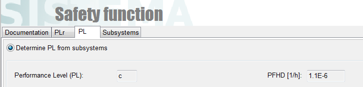
We can now return to our SF function to be sure (I have STO) and see in the PL tab that in fact our entire SF has the PLc level.
Let’s check if we can maintain this PL level by using category B instead of 1. In the SB subsystem tab (in my case, Test), in the Category tab, we select B instead of 1. We see that we have lost our SF – it is not possible to obtain the PLc level with category B.
Looking at the BGIA publications, we can see that it is actually so (for category B, the maximum level we can get is PLb). The main difference is the possibility of using elements not tested for safety in category B, the structure of SF is similar to that in category 1.
And that’s it for the introduction to the design of safety functions in SISTEMA. I am aware that a lot of information has not been fully explained, nevertheless I believe that a rich quality literature will dispel many doubts in this regard. In subsequent articles from this series, I would like to focus on discussing more interesting SFs in the field of electric drive control (extension of the examples provided in the IFA Report), using SISTEMA for this will significantly facilitate the calculation of the necessary parameters.
Author: Łukasz B.