PLC ( Programmable Logic Controller) – a universal microprocessor device designed to control the operation of a machine or technological device.
This is what the contemporary online encyclopedia claims. But why they were created and what are they used in practice for? At the beginning a little bit of history…
Until the late 1960s machine control was based on the “relay-contactor” technique. The modern ladder known from the PLC replaces wiring between contactors, relays and other special elements. Everything was placed in the control cabinets, so you can imagine how big they must have been. This solution had many disadvantages:
- Inaccurate contact and high wear of components.
- Difficult assembly and connection of a large number of different types of elements.
- Difficult modification of cabling after changing the control.
As a result, PLC controllers quickly began to be used on a large scale as programmable controllers in production plants and installed in production lines in order to factory production (FA).
Comparison with relays
| Type of PLC controller | Type of relay | |
| Function | Programs enable complex control to be achieved. In addition to original sequence control, PLCs also enable a wide variety of functions such as analog positioning, data processing and communication. | Complex control using a number of relays is difficult from the standpoints of economy and reliability. They basically offer on/off control only. |
| Flexible control modification | Can be altered freely by modifying the program. | There is no alternative other than to modify wiring. |
| Reliability | High reliability and long life. (Basically all semiconductors.) | Since relay contacts are used, they may develop poor contacts and have a limitation of life in the case of prolonged use. |
| Ease of maintenance | Equipment failure can be monitored by peripheral software, etc. PLC modules can be replaced individually. | It is difficult to find the cause and replace when there is a relay failure. |
| Support for large scale and complexity | Offers more flexibility and extendibility than the relay type. | Use in large scale becomes impractical in terms of time and operation. |
The role of PLCs is to enable sequential control via the program. Generally speaking, it is a dedicated controller (computer type) that controls output devices according to a fixed program based on signals sent by input devices. The program is based on the operation of input and output relays. The external input signal can be understood as pressing the button (PB0) and the output signal as switching on the indicator (L).
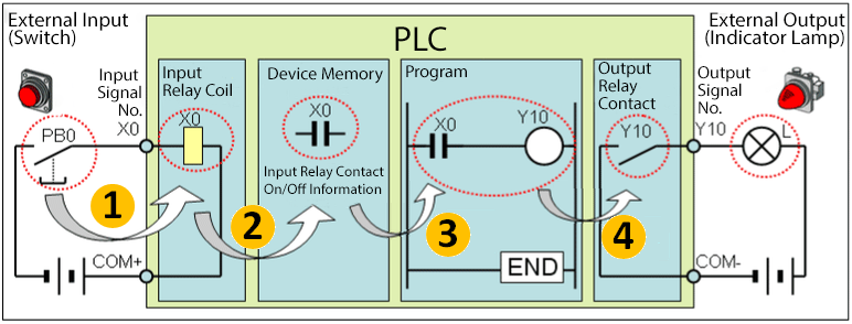
Basic operation rules:
- When external input switch PB0 (contact) connected to PLC input pin X0 shown on the left side of the figure avove closes, current flows to the coil of input relay X0. The input relay coil changes according to the status of external input equipment, andf does not exist in program.
- When current flows to the coil of input relay X0, information is imported as relay X0 contact “on” information to the PLC internald evice memory area and is saved. In different words, “on/off” of input relay contact X0 used by the program corresponds to that input pin X0 of the same number.
- Information from the input relay contact Xo in device memoryis “switched on”, so the output relay coil Y10 is also “switched on”
- Output signal No. Y10 corresponds to “switched on” status of the output relay coil Y10 with the same number, so the indicator lamp of the external output equipment is therefore also “on”.
Names “coil” and “contact” are used figuratively. In practice the signals are given on the controller inputs through different electronics elements i.e. RC filters or optical isolators.
Types of connections
Ladder diagrams that are easier to understand than a command language program are often used when creating PLC programs. As in the electrical schemes, all elements are connected in series or in parallel. Below you can see various types of connections and devices used in GIX Works3 software from Mitsubishi.
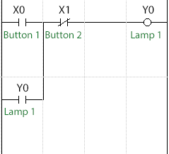
The following picture is an example of a program that implements the light (output Y0) when both buttons (inputs X0 and X1) are switched on. Next to the fragment of the ladder, the interpretation of the operation in the electrical scheme is presented.
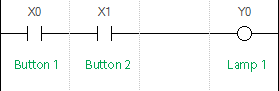
Both switches are connected in series, which suggests that they present the condition “AND”. After entering the “high state” on inputs X0 and X1, i.e. after switching on the buttons (see electrical diagram), the output Y0 will be switched on (see wiring diagram).
Another example requires the inclusion of any button (inputs X0, X1) so that the lamp (output Y0) turns on. Below is an example in the ladder and wiring diagram.
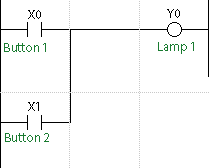
Switches are set in parallel, this connection presents the condition “OR”. After entering the “high state” on inputs X0 or X1, i.e. after switching on one of the buttons (see electrical diagram), the output Y0 will be switched on (see wiring diagram).
Contacts b (normally closed)
The controller input can work both as a normally open contact (NO) and as a normally closed contact (NC). To change its operating mode, simply use the appropriate contact in the program. The self-sustain function with a closed contact is shown in the following diagrams.
When you turn on the X0 button, the Y0 lamp will be turned on even if the X0 button is turned off. This is due to the parallel connection of input X0 with the contact Y0. When the output Y0 is switched on its contact also, which will act as self-supporting. Turning off the Y0 lamp will only occur when the circuit is interrupted due to the closed contact of input X1. To change the first two examples into a self-sustaining function in the PLC, all you have to do is use the digital input NC contact and the Y0 output contact. For such a function to be carried out without using a controller, we would have to use an additional relay K1 and replace the button with an NC contact. I do not have to explain what is easier, faster and cheaper.
Coils with memory
In addition to ordinary coils, which are active only when there is a signal, there are memory coils.

In the above diagram, the X0 input activates the SET function, that is the state of high output Y0. Input X1 activates the RESET function, that is the state of low output Y0.
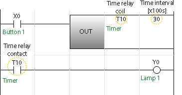
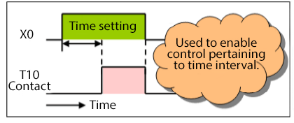
Time relays
The time relay in the PLC uses “start delay relays”, where the coil contact is “switched on” when the time relay coil conducts current for a longer time than the preset one. If the coil is “switched off” even for a short time, the timer will reset and its contact will also “switch off”. The set value of the time relay is a multiple of the waiting time, usually expressed in 0.1 second intervals. The marking “T10 30” in the figure below means that the time setting of the time relay with the number T10 is 3 seconds.
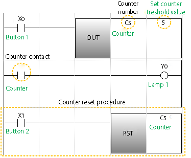
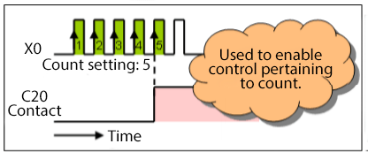
Counters
The counter in the PLC counts the repeats of the change of the input signal from “low” to “high”. The counter contact is “switched on” when the number of repetitions reaches a predetermined value (counting up). When the counting is completed, the value does not change and the output contact remains “on”. When the counter value is reset, it changes to 0 and the contact is “switched off”. In the figure below, the designation “C5 5” means the set value of the counter No. C5 to “5” repetitions.
With basic controller devices, i.e.: inputs, outputs, time and meter relays, there are also internal relays. M markers. These are additional relays equipped with coils and contacts that can be used in the program without restrictions. Pressing the switch is saved in the memory and used as a signal or status symbol.
The above list is a basic equipment. The range of available devices is much larger. Example: internal relay (Mx designation: “x” means the number that corresponds to the sequence). Internal relays are additional relays equipped with coils and contacts that can be used in the program without restrictions.
The information presented above is just a tip of knowledge that you can get at PLCs. In the following articles you will see what the configuration of the controller is and how it will be launched. From connecting it to the power supply, by retrofitting it with extension modules, up to visualization in the HMI.
Author: Grzegorz T.
I have been meaning to post something like this on my website and you gave me an idea. Thanks.