Simple control systems use only digital inputs and outputs of the PLC. The digital inputs are used to collect two-state information from the object and digital outputs to control the on / off type. In more complex control and regulation systems, and where any process begins, it is necessary to use analog inputs and outputs.
INTRODUCTION
Analog measurements provide information to the PLC with the value of the measured quantity, e.g.
- Pressure [bar, MPa …]
- Flow [m3 / h, hl / h …]
- Level [m]
- Temperature [ºC]
- Distance [m]
- Frequency [Hz]
- Current intensity [A]
- etc.
Before the measured value goes to the controller, it must be converted to an electrical signal and then to a digital value. The conversion of the physical quantity into an electrical signal takes place in the measuring transducer (sensor). The electrical signal goes to the PLC where it is converted to a digital value understandable for the PLC program. Let’s analyze this on the example of pressure measurement in the tank.
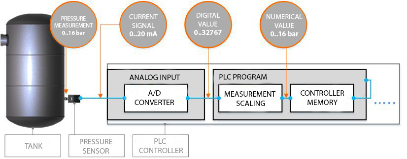
A pressure transducer with a range of 0..16 bar has been installed in the air reservoir with a 0..20 mA current output. The current signal was connected to the analog input of the PLC. Let’s see the path of such a measurement from the physical value to the value understood by the user (operator):
- The sensor measures the pressure in the range of 0…16 bar and converts it into the 0…20mA current signal.
- PLC controller on the analog input receives the signal in the range of 0…20mA and converts it into the digital value, e.g. 0-32767 – it depends on the type and configuration of the PLC controller.
- For a PLC programmer, it is the digital value that reflects the measurement of the physical quantity, e.g. pressure. To further use this measurement, the PLC programmer must scale it according to the measuring range of the pressure sensor. The scaled value is saved in the controller’s memory.
- Further use of the scaled measurement depends on the needs, these can be:
- generating an alarm (e.g. overpressure),
- displaying the pressure value for the operator in the HMI panel or in the SCADA system,
- using the measurement for the regulator’s feedback,
- doing something after exceeding the limit, e.g. opening the valve.
- etc.
The accepted standards for electrical signals in analog measurements are:
- 0…20 mA
- 4…20 mA
- 0…10mA
0..20 mA , 4..20 mA, 0..10 V ANALOG MEASUREMENTS
We can hear about several standards of electrical signals of analog measurements. But in what aspects they are different? In industrial automation, the most common electrical signal of analog measurement is the 4…20mA current signal. This results from the ease of use of this signal and the relatively higher resistance to interference than the voltage measurement 0 … 10V. In the 4 … 20mA signal it is easier to detect a cable break between the sensor and the controller. The cable break is detected if the current drops below about 3.8 mA. In the both measurement of 4 … 20mA and 0 … 20mA, the short-circuit at the sensor output is detected if the current value exceeds approximately 20.5 mA. The detection of such defects must be taken into account in the PLC program.
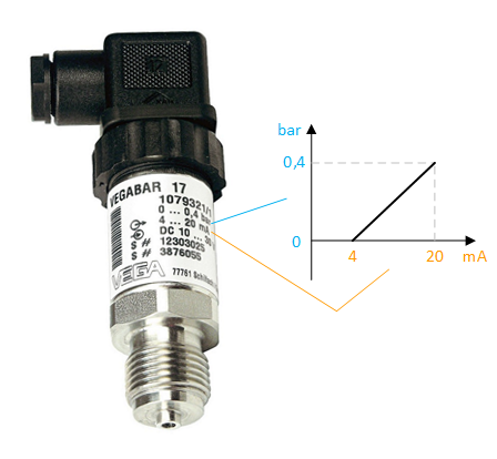
On most measuring transducers you can read what is their measuring range and electrical output. The figure below shows an example of a pressure transducer with a range of 0 … 0.4 bar and a current output of 4 … 20mA. The chart shows the relationship between these two ranges.
ANALOG SCALING IN PLC PROGRAM
Let’s install the above sensor with the range of 0 … 0.4 bar to our tank and connect its output 4 … 20mA to the analog input 0 … 20mA of the Siemens S7-1200 PLC. Let’s see how it looks in theory:
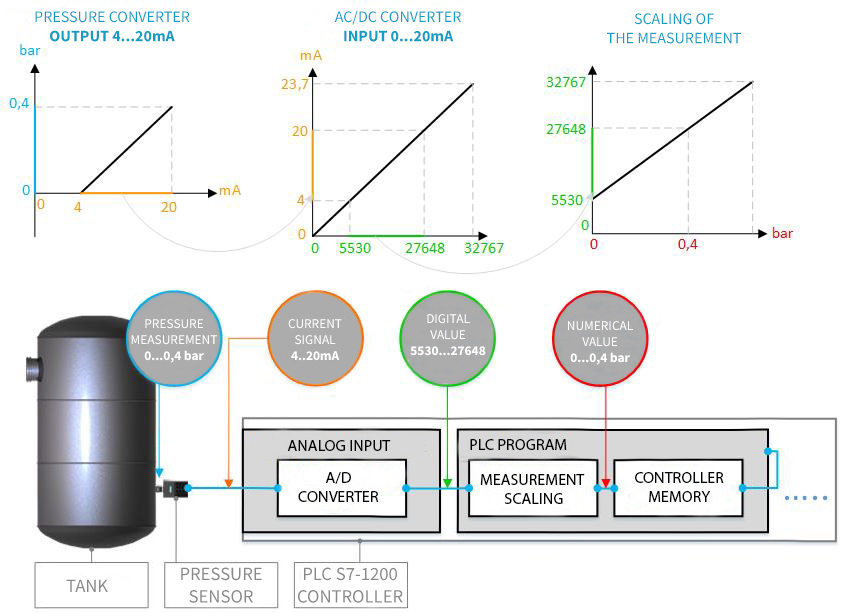
The analog input 0 … 20mA in the S7-1200 controller actually works in the range of 0 … 23.7 mA which reflects the range of the digital value from 0 to 32767 at the AC / DC converter output. If we connect a sensor with a current output of 4 … 20 mA to such an input, the digital value for 4 mA will be 5530 and for 20 mA will be 27648.
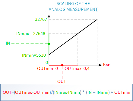
To obtain the actual numerical value of the measurement, it is necessary to make calculations according to the above formula. In some controllers there are ready functions for scaling analog measurements and in some it is necessary to build such a function by yourself. The S7-1200 controller does not have a ready function, but we can use the CALCULATE or SCALE_X + NORM_X option, the Unitronics controller is ready for the LINEAR function and in the ALLEN BRADLEY controllers it will be the SCP function.