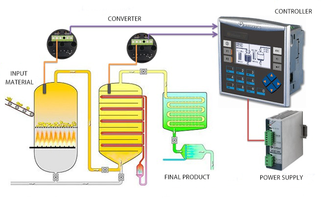
When we talk about a process, we mean any installation in which the input material is processed in a controlled and automated process into a semi-final or final product. In many cases, some supervision and control is carried out in a room or building other than the one where the physical production takes place.
The operation of the control system in industrial processes is based on 4-20mA loops, which constitute a simple analog communication interface that enables the transmission and reading of a single measurement signal. For many years they have been one of the most common standards in industrial control systems, known and used for several dozen years.
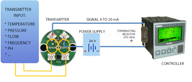
The control loop system usually consists of the following components:
- Transmitter inputs to which the signal from the sensor is connected;
- Transmitter outputs where we get 4-20mA signal;
- 24V power supply;
- 250Ohm terminating resistor;
- Process controller.
As statistics show, automation engineers spend about 70% on the troubleshooting in 4-20mA loops, 20% on commissioning new installations and only 10% on process calibration. In this article, we will take a closer look at the aspects of troubleshooting.
It is worth noting that basic diagnostics in the 4-20mA loop consists of the following stages:
- Measure – voltage and current;
- Simulate – input signal to the transmitter;
- Use the source – 24V voltage;
- The most common problems in 4-20mA loops include:
- Wiring Problems: Poor terminations, inadequate insulation, corrosion and oxidation on the connectors can adversely affect the performance of the wiring in the 4 to 20 mA loop.
- 24V loop power supplies: Defective or overloaded power supplies can cause the mA loop to function erratically or fail completely.
- Damage to the controller inputs: If the mA signal is correct, but the controller is not interpreting it correctly, then the process control is disturbed.
- Transmitter damage: If the transmitter does not change the mA signal in order to correctly respond to the measured signals from sensors / sensors, the control process is disturbed, as in the above case.
- Defective sensor.
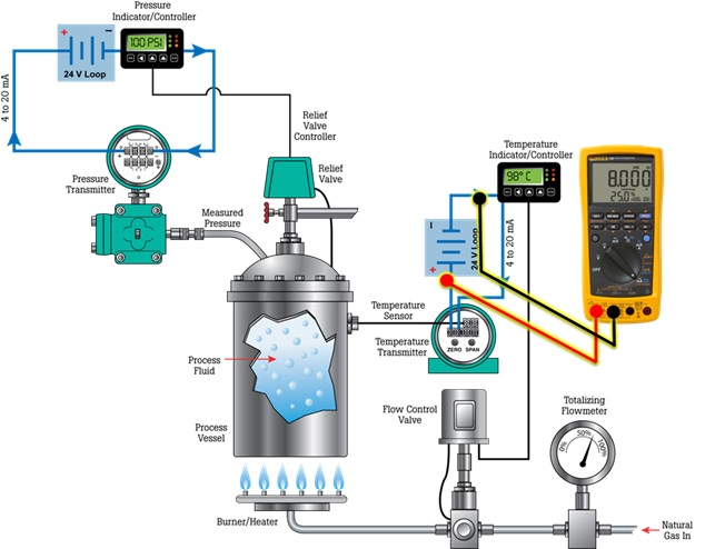
One of the first steps in testing is checking the power supply. If during the measurements on the power supply output we find full 24V, it is probably working properly. If the power supply is overloaded, this could be the source of a problem with the control loop (Picture 3).
It is also worth checking the thermal conditions in which the power supply operates. The ambient temperature at which he works will have a negative impact on the stability and reliability of his work.
If it is suspected that the 24V loop power supply is faulty, the next step is to use the power source from the control loop calibrator. To do this, disconnect the wires from the power supply output and connect them to the appropriate terminals of the calibrator (Picture 4). Please note that this type of diagnosis should not be carried out continuously. Cheaper calibrators can be overloaded with a longer 24V signal.
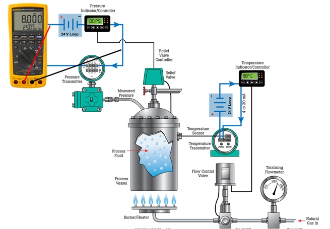
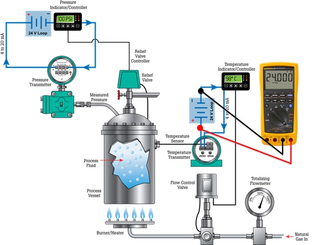
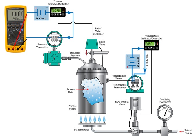
Let’s assume that the power supply is working properly, so the next step in diagnostics is measuring the signal at the transmitter output. Remember that before we start this measurement, we must first call the dispatcher to stop this part of the process. Why? This measurement requires the calibrator to be connected in series with the loop (Picture 5). After connecting a multimeter or calibrator, the loop is closed again and the process can be restarted to perform a measurement.
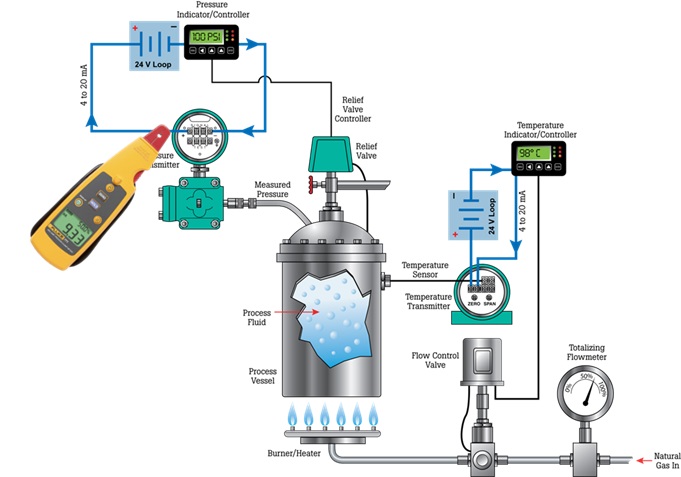
It can be troublesome to stop and start the process to measure loop current in 4-20mA. However, this will allow a similar situation to the one in which the process is run continuously. Measurements in the 4-20mA loop can be carried out using dedicated clamps adapted to measure the DC signal and small values. In this case, the loop remains intact, the process continues continuously, and the measured value can be read from the actual situation (Picture 6).
The last step in tracking problems in the 4-20mA loop is checking the transmitter input (Picture 7). For this purpose, a calibrator should be used, which will enable the simulation of the sensor signal with which we are in contact in a given situation. Many of the calibrators also allow you to set threshold values for a given type of sensor. This will allow for accurate process supervision and signal simulations from 0% (4mA) to 100% (20mA).