I would like to introduce you to the small series of articles about using Motion Control blocks in Siemens S7-1200 controller. I’ll write about the whole axis configuration process, connecting the drive and we’ll try to control our motor in many ways.
Motion control in S7-1200
In S7-1200 we have the possibility of using already prepared instructions for controlling the stepping motors and servo drives. The simplicity with which we can configure the axis and later control it it makes it really worth to be interested in this technology. In a very fast way, we can perform axis positioning, which will work well in many applications. Personally, I had contact with several machines in which Motion Control blocks were used to control the hydraulic axis! The analog output controlled the hydraulic proportional valve, and the ruler returned the current axis position to the controller.
The control can take place in three different ways these are pulse PTO outputs, analog outputs or a PROFINET network. However, at the very beginning we will only deal with PTO outputs and stepping motor. It is the cheapest solution that each of you will be able to try out in home conditions. PTO outputs enable easy control of stepping motors. Most stepping motor controllers are equipped with STEP and DIR inputs, i.e. step and direction. Control of such a motor consists in generating impulses that are fed to the STEP input. However, the DIR signal determines the direction of rotation of the motor.
A little bit of theory
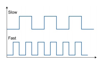
OK, but what are these PTO impulses? I’m sure that everyone knows that the PWN signal is. In this signal we have constant frequency, but variable filling. In the PTO signal we have opposite situation. Our filling is constant and is 50%, and the frequency of this signal can be regulated. The higher it is, the more impulses we give to our controller and the faster our motor revolves.
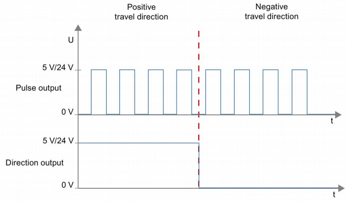
The direction of rotation is determined by the DIR signal. However, it is important that the change of this signal occurs sufficiently sooner than the next edge of the STEP signal. Occurrence of both edges at one time does not guarantee that the motor will turn in the direction we want. Fortunately, in our case, S7-1200 deals with the generation of both signals and it will be he who will ensure that the generated signals meet the required standard.
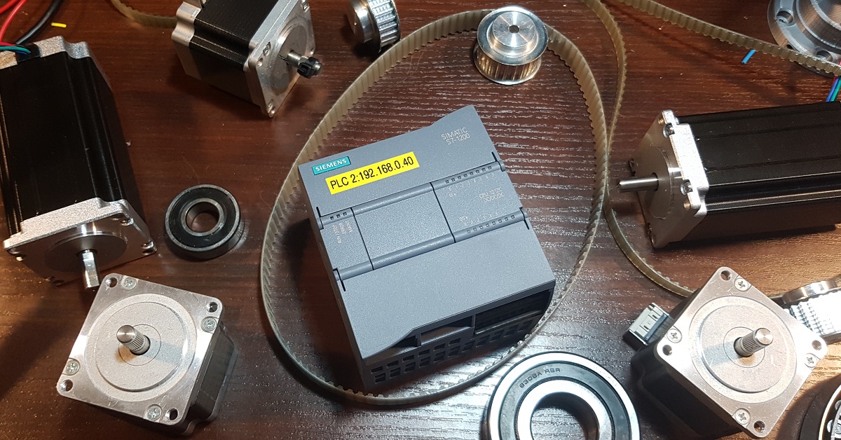
Test station
All of the examples will be based on the controller version 1215C from firmware 4.1 and TIA Portal V13 software. If you have different version, you will be able to perform these examples, but some differencies may occur. First of all, depending on the controller firmware, you can have more or less functionalities. First version of Motion Control was very poor but through the time they have developed a lot. For example, only from version 4.0 we have the possibility to choose on which outputs exactly the step and direction signals will be generated. Earlier, these outputs were set permanently and sometimes it caused some problems. Secondly, the version of the controller itself also introduces some limitations that result from the number of available outputs. In my controller I can drive up to four stepper motors, while in the controller 1211C we can connect only 2 stepper motors.
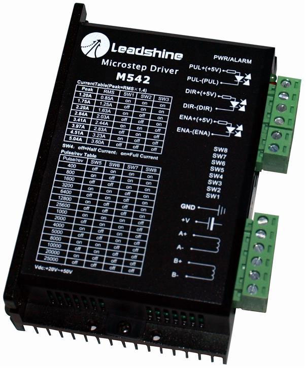
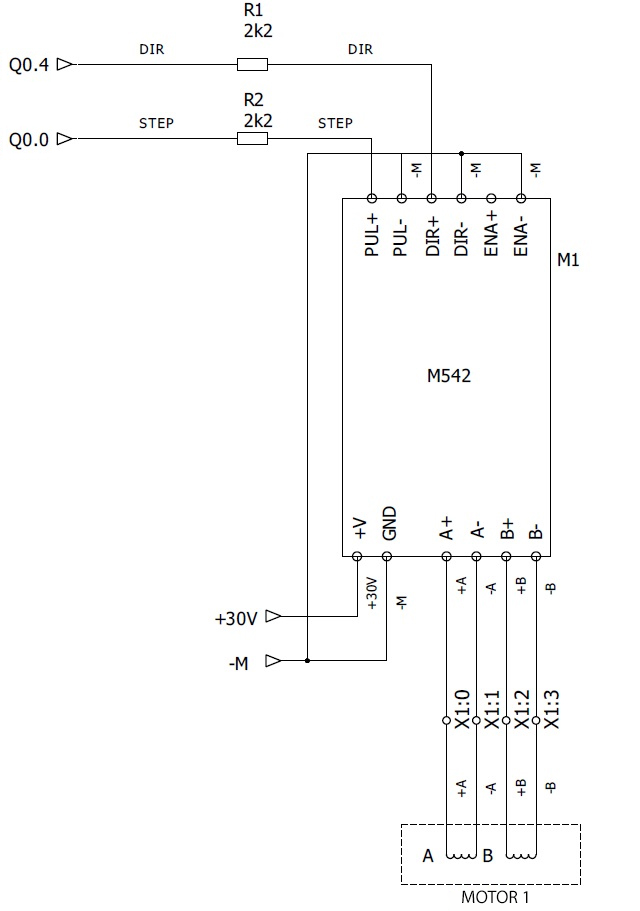
For the role of our stepper motor controllers we will use very popular in the world of amateur designs CNC – M542. These are relatively cheap controllers that have really decent parameters. Of course, we could use something cheaper for our tests, but I leave it to you. Remember only about the correct selection of the controller for your stepper motor.

Cablelogy….. how to connect everything in one piece.
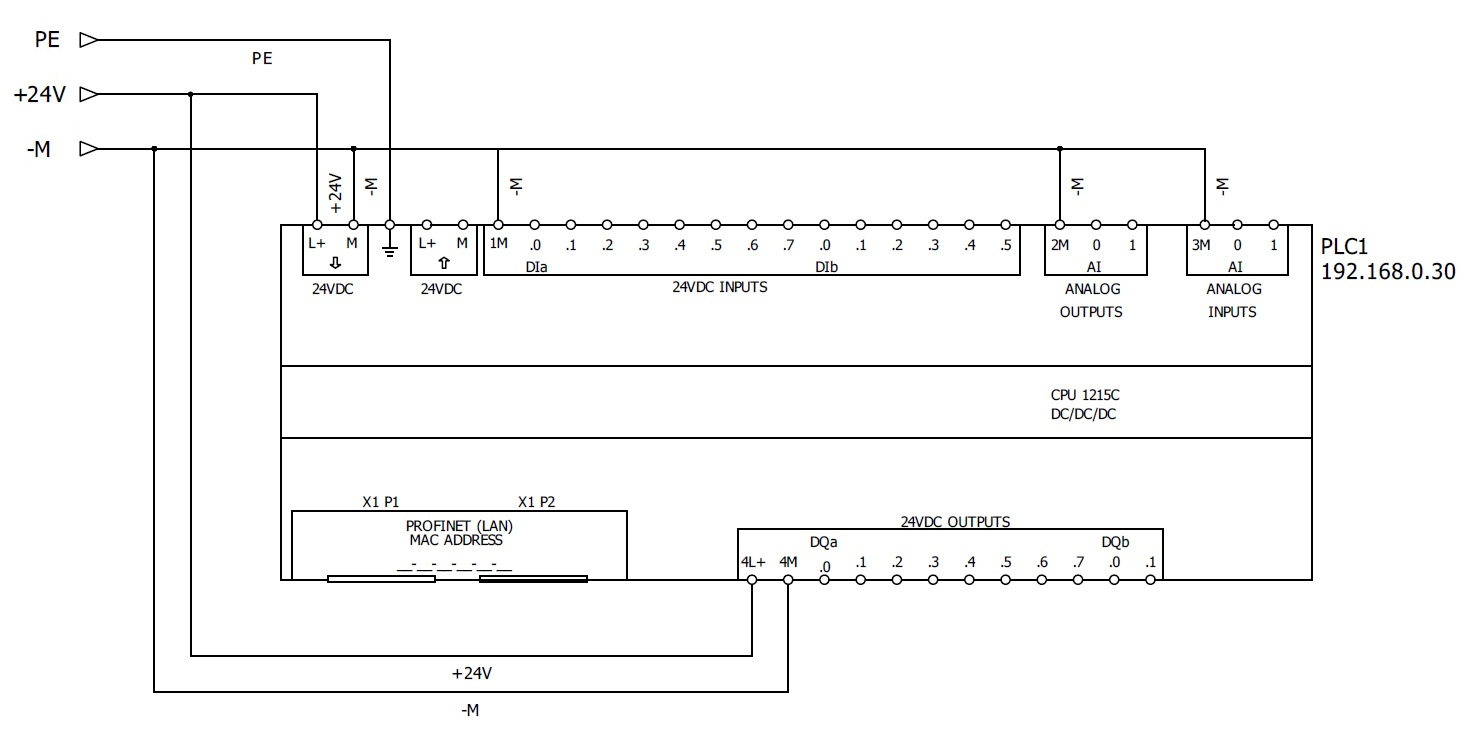
We don’t have to talk about PLC controller. We connect it in the same way as in every application.
Some doubts can occur in the case of stepping motor controllers. All these controllers have very similar structure, but I will write only about my specimen. It has 12 clamps. Two of them are the most important – power supply. The manufacturer requires that it should be powered by the voltage with the range of 20-50V DC. In this case it will be 30V, because this is the maximum that I am able to get from my power supply.
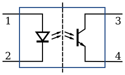
Another four clamps are the motor connections, the last six are the control signals and that’s where some problems may occur. . Because on our controller we clearly see the descriptions – PUL + (+ 5V), DIR + (+ 5V) and ENA + (+ 5V). Where did 5V come from?! Where do I get this tension from ?! Ok … let’s calm down, take a few deep breaths and let’s look into the documentation of our controller. Yeah, now we know what’s going on. Each input has a galvanic isolation made on a transoptor. The optocoupler is nothing but a LED diode and photosensitive element in one small housing. Signals at the input cause the emission of light, which, by falling on the phototransistor, forces the current to flow.
As we all know, when connecting such a diode, it is necessary to limit the current flowing through it. Why? It results from its construction. A diode is nothing but a semiconductor connector that has polarized in the direction of conduction has minimal resistance. If we directly connect the voltage to it, the current flowing through it simply burns it. The controller’s manufacturer also knows about it and that’s why he used a 270 Ohm resistor on each input. Such resistance causes that at 5V, a current sufficient to drive it will flow through the diode. However, these 5V comes from the fact that many controllers work on such a standard. This solution of the manufacturer does not bother us at all, because we only need to add a resistor in series, or at least we get a controller in return, whose inputs we can easily adapt to different voltage levels.
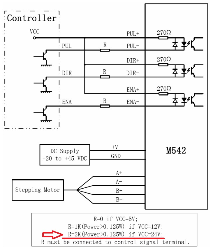
The manufacturer even presented in his documentation what values must have resistors attached by us to adapt it to a given voltage level:
Since we already know how to connect our controller, we can use our knowledge in practice. I’m planning to connect 4 stepping motor controllers to my PLC controller. For now we will use only one, but later we will try to execute an application with multiple axes. At this point, the choice of outputs that we will use is a very important issue. The original setting of our PTO outputs is that PTO1 uses Q0.0 and Q0.1, and PTO2 uses Q0.2 and Q0.3. Is this a good solution? If we have only two motors, yes. We can leave it this way. But if we use 3 or 4 PTO outputs, then we may have a small problem. It must be remembered that only the first four outputs can generate pulses at 100kHz. The next outputs are pulses with only 30kHz frequency. We must therefore correctly assign our control signals. The first four will be STEP signals, while the next four are DIR signals. For example, the PTO1 output, which will handle the first axis, will have the step output set to Q0.0 and the direction output will be set to Q0.4.
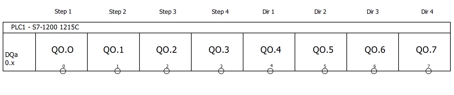
Are you wondering why do we we have to change the outputs? All this is due to the fact that we need really high frequencies at the STEP outputs. Even those 100kHz sometimes may not be enough for us. However, slower outputs can be used as a direction signal without any problem. Have you ever seen an application where the motor would have to change its direction faster than 30 thousand times per second? Me neither 😉
S7-1200 configuration
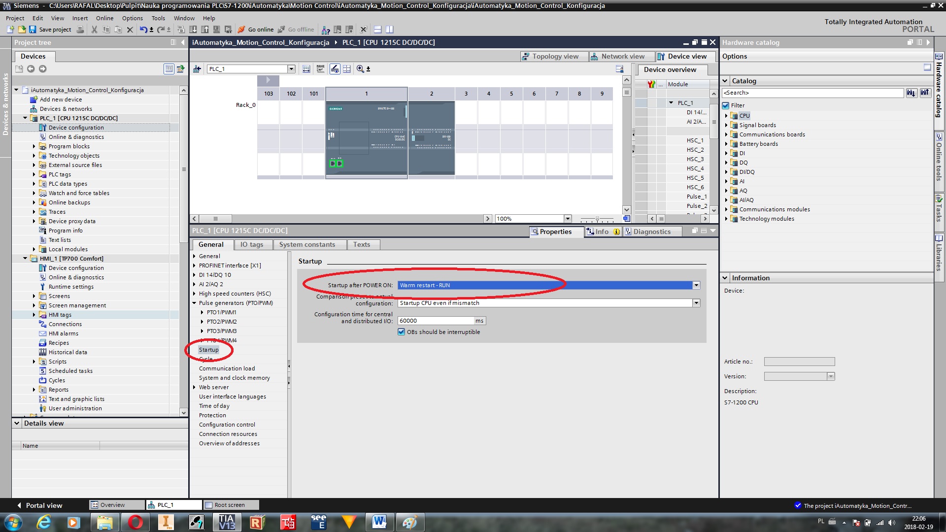
Since we already have electrical connections, we can take care of the controller configuration. Create a new project now and add your controller to it. The first thing we set is the parameter Startup after POWER ON. It has nothing to do with Motion Control technology, but I would like to alert you not to leave this parameter without interference. It was initially set to Warm restart – Mode before POWER ON. This means that after starting the controller, it will return to the state before the power failure. Can you see the problem? There are some errors, after which the controller goes into the STOP state.
Such errors are rare, but their occurrences can never be completely ruled out. In such situations, machine operation usually tries to turn off the machine “on the main”, but unfortunately with this setting, resetting the driver will not help us. The driver will still be in STOP. If you do not want to drive behind your machine to the other end of Poland, just to click on RUN in the TIA Portal, I recommend changing this option to Warm restart – RUN. This will cause that each time the controller is started it will be set to RUN mode. Even if it was in STOP before it was turned off.
This parameter can be found in the Startup tab in the controller configuration:
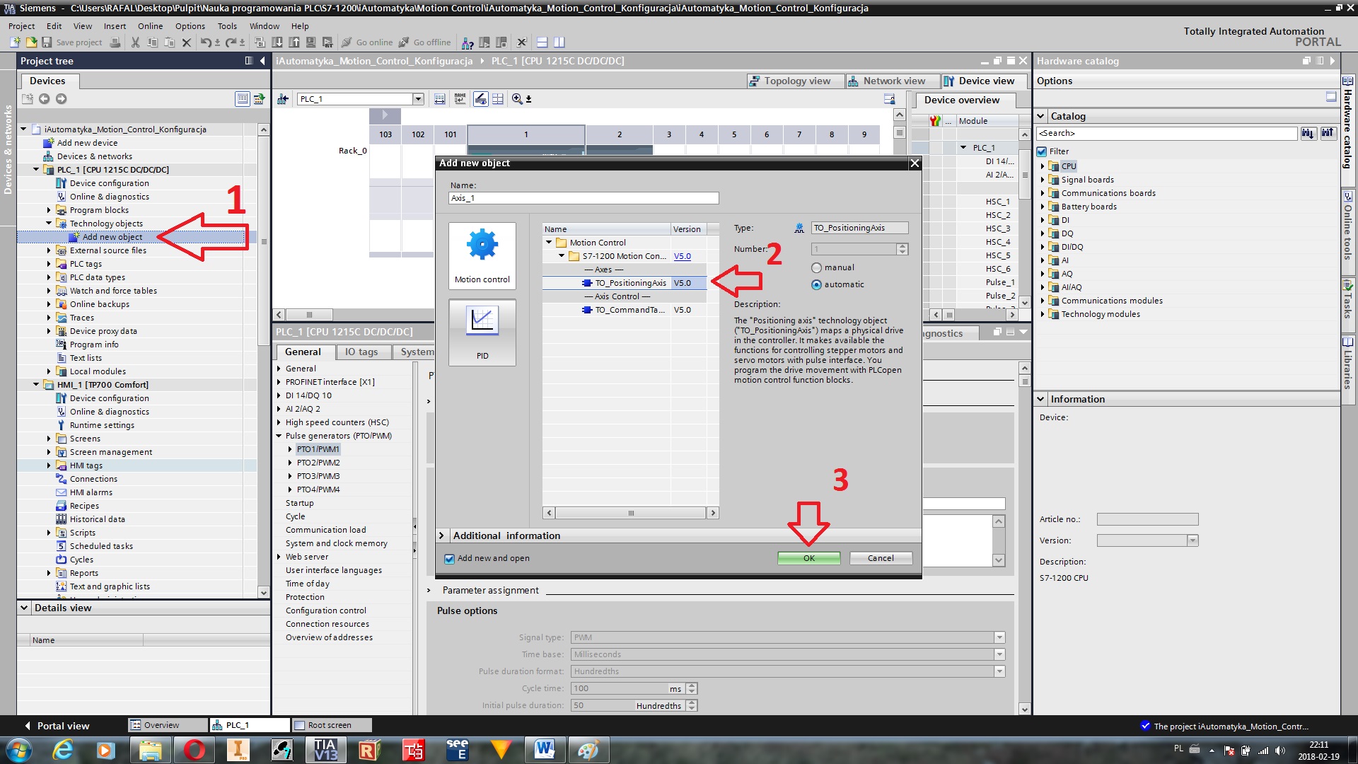
Ok, let’s add our first axis. In the project tree there is a Technology objects tab. We click on in and choose Add new object. Window with TO_PositioningAxis will open, and then we confirm it by pressing the OK button.
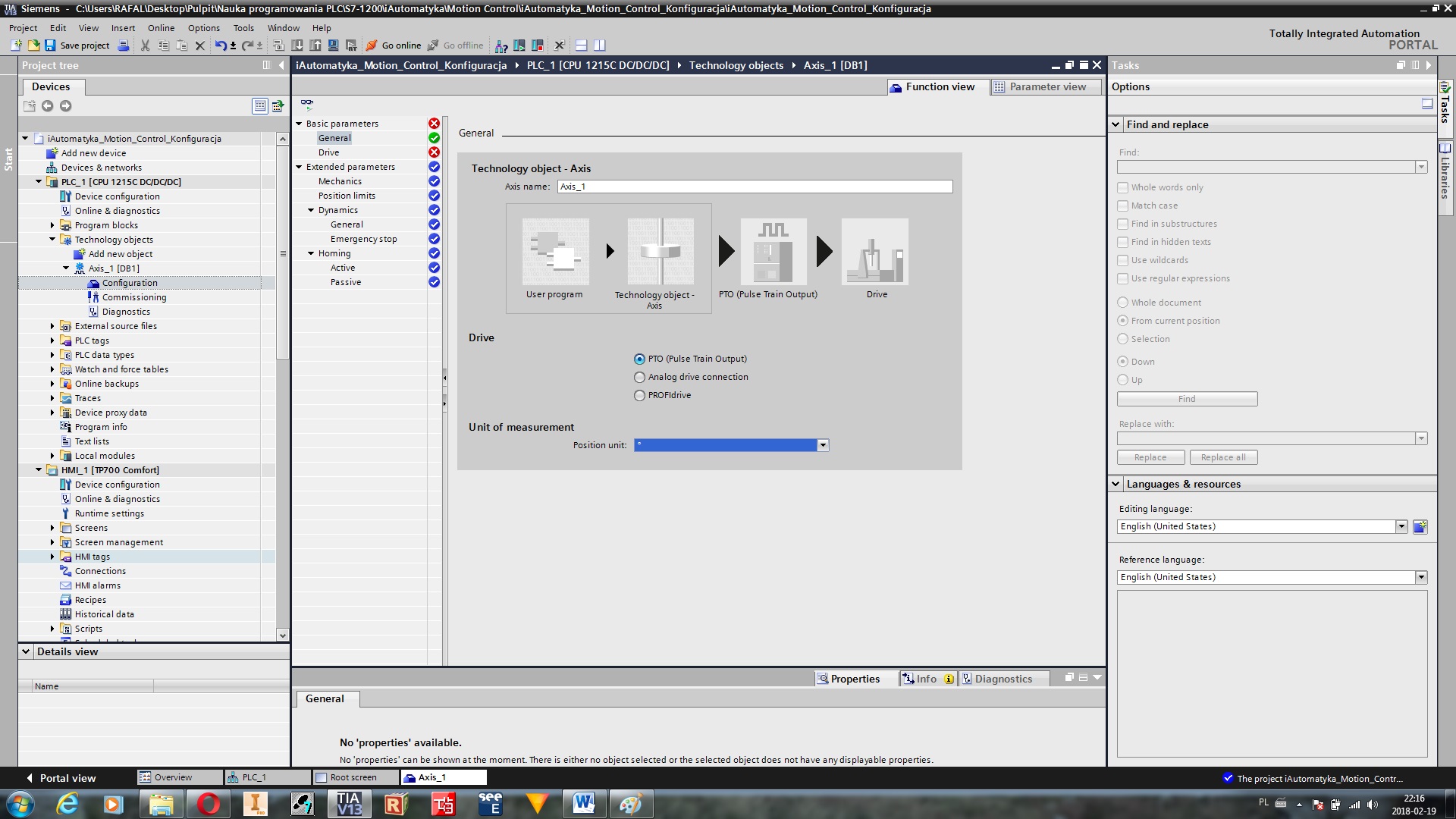
We’ve just added the first axis to our projects. In the first tab we can set three things. First of all, we can change the name of our axis, if we haven’t done it in the previous window. Secondly, we can choose the type of our drive. We’ll be performing our tests on the stepping motor, so we have to choose PTO (Puls Train Output). The last thing are units, which will describe the position of our drive. Let’s set our first axis as a rotary axis.
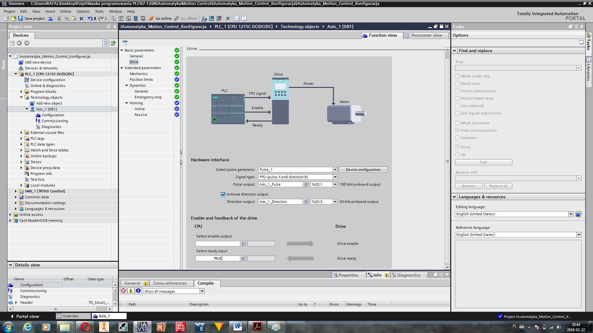
In the second tab we configure our drive. This is the first axis, so we will also use the first PTO output. It doesn’t really matter, but we have to keep the orneriness in our project. As the STEP output we choose Q0.0 output, and as DIR output we choose Q0.4. At the very bottom we have the possibility of assigning two signals. One of them is a signal switching on our drives, and another one is a signal confirming their readiness.
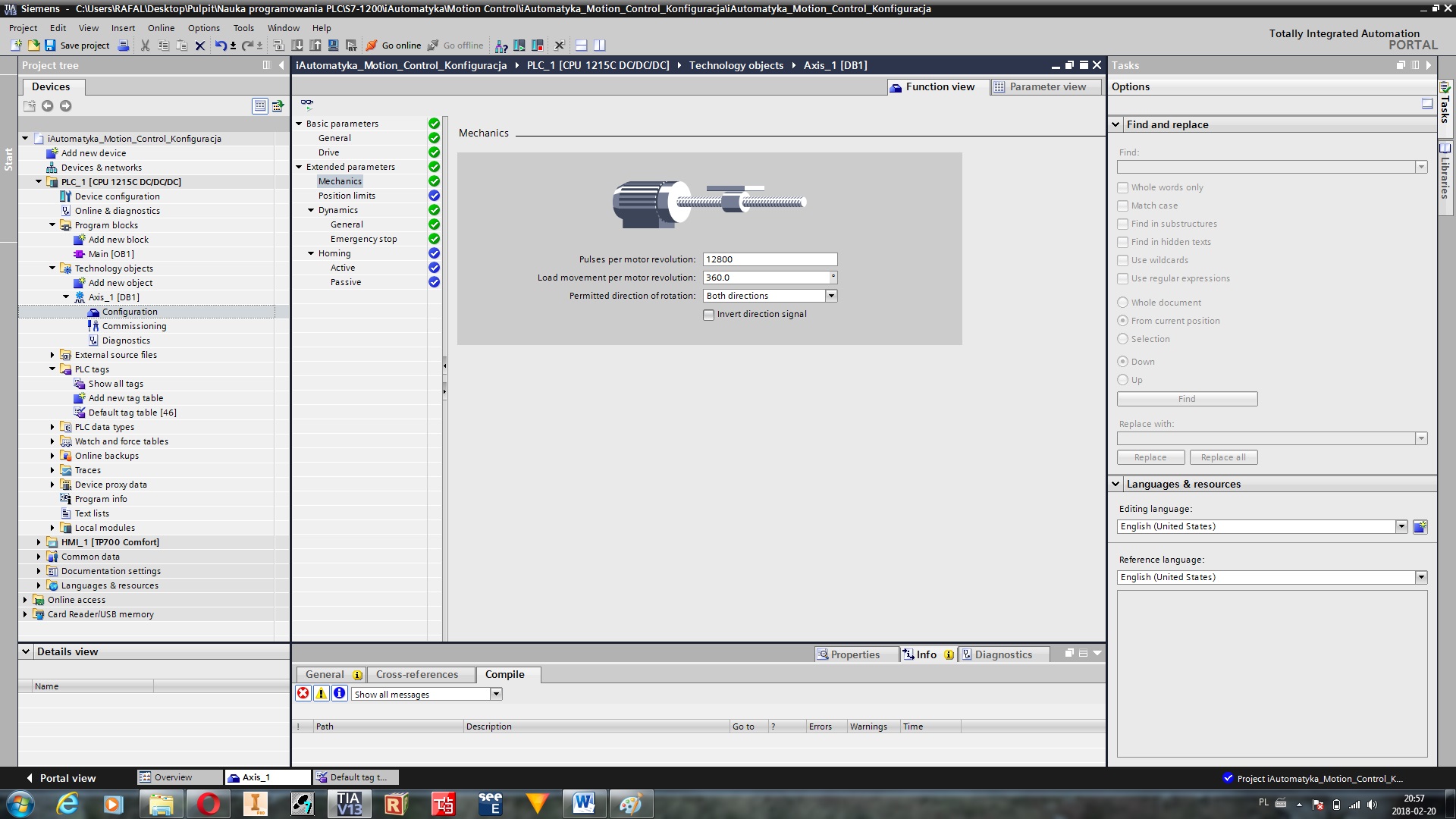
It’s time to define the mechanical part of our drive. In Mechanics tab there are four configurable parameters. The first one determines the number of pulses needed to perform one full revolution of our motor. We have to take into account both the motor parameters and micro step set on the controller. For my motor one step is one 0.9° revolution. It means that one full revolution needs 400 steps. Now I’m going to divide it by my micro step (1/32) and I have the value of 12800. The second parameter determines which path the moved object will travel when performing one full engine revolution. In different words, this parameter determines our gear. For the tests we will use the motor without any gear, so we write there 360°. The third parameter is for setting direction of revolution of our drive.
We also have the possibility of setting our axis. We have at our disposal two hardware switches and two program switches. What are their differences? Hardware switch is just a physical limit switch installed on our machine. After starting the operation, the drive has to stop immediately and does not allow for the next move. It is basically the last protection of our axis from possible mechanical damages. For proper operation of the software switch, it is necessary to properly reset our axis. However, we will leave these options unconfigured for now. We will deal with them during the practical application of Motion Control.

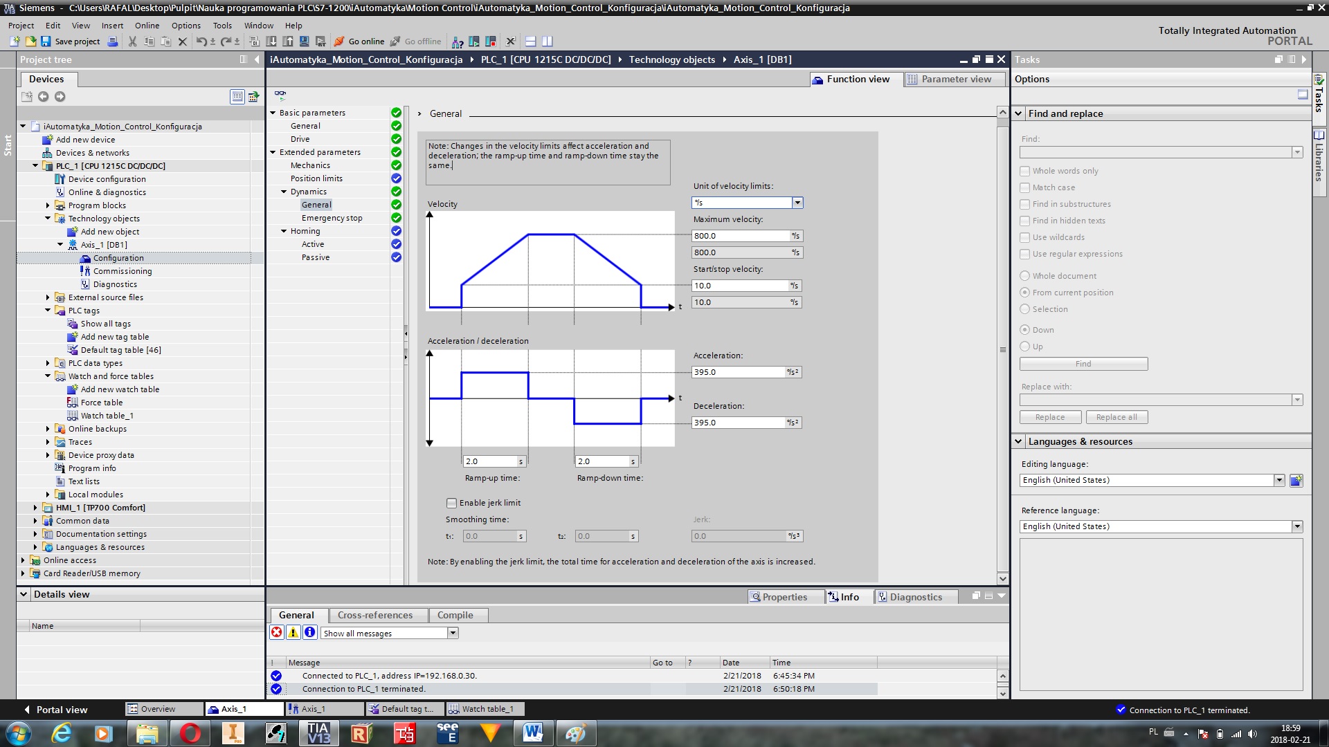
The last parameter discussed today is the dynamics of our drive. We can freely configure acceleration and braking ramps. Maximum and minimum speed. Stepping motors does not perform well at very low speeds, because there are large vibrations of such a motor. If you want to maintain smooth motion, it is necessary to set the appropriate minimum speed. This effect can be minimized by using a larger micro step.
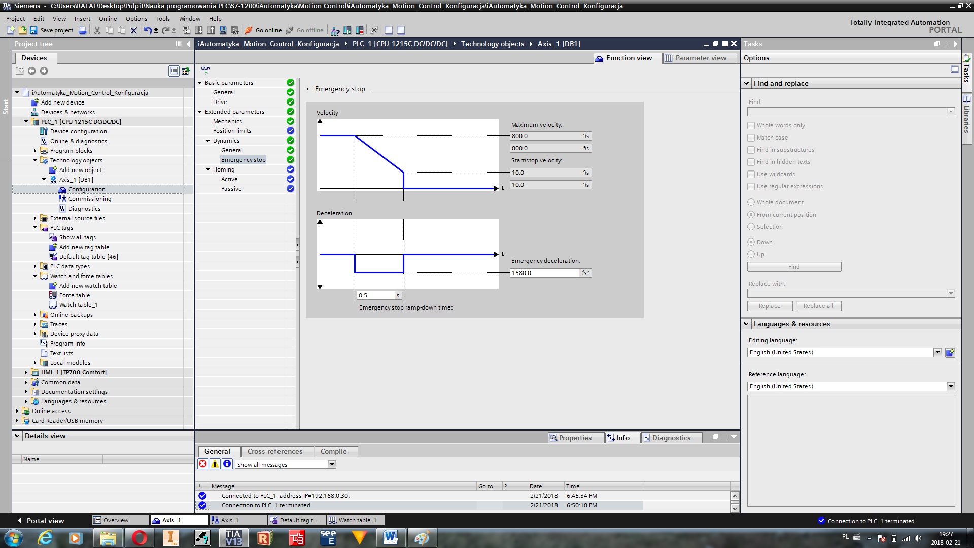
The emergency stop settings are the particular dynamics parameters. We define in them the time after which our drive will brake from the maximum speed to the minimum speed. This time should be as short as possible.
The last parameters determine the ways of zeroing the axis. However, we will try these settings on the actual layout in the subsequent episodes of the series.
Axis test
Our first axis in S7-1200 has already been configured. But how do we know that it’s workig properly? For this purpose we will use the Commissioning tool. But first we have to upload our configuration to the controller. If you tried to play with Motion Control, then probably in this moment you had some problems. Is is important to follow two rules. The first one is: during uploading the programor configuration we always stop our controller. TIA Portal not always demand the stopage of the controller and then new parameters of our controller will not be loading properly. The second rule: if something does not work as it should, then we set our driver in STOP, and then in RUN. This combination solves 99% of problems with Motion Control blocks 🙂
Ok, if we have already uploaded the configuration to our controller, then we can finally move our axis. In the project tree, select the created axis, and then open the Commissioning (1) tab. We are given a panel for manual control of our drive. We now activate our drive (2) and wait for the connection to the controller. At the end, we turn on the axis (3) and in this way we gain control over our drive.

On the left side of the panel we can choose 3 tabs: Jog, Positioning and Homing. In the Jog tab we can activate the axis move to the left or right side. In Positioning tab we can set our axis into a specific position, and in Homing tab we can zeroing our axis. Zeroing is important when we want to make an absolute movement (movement into a specific position, not offset by a set value).
If the whole configuration was successful, your drive should come alive. Controlling it is so simple that it does not require a deeper description.
Author: Rafał L.