It wasn’t easy at all! There was no good description of the program, there were no pages in the documentation, and there was no time or opportunity for efficient change. But it worked! 72 inputs and 48 outputs from the old PLC. A story about how I replaced the Simatic S5 PLC from the late 70s for the newer Siemens S7 with the HMI operator panel.
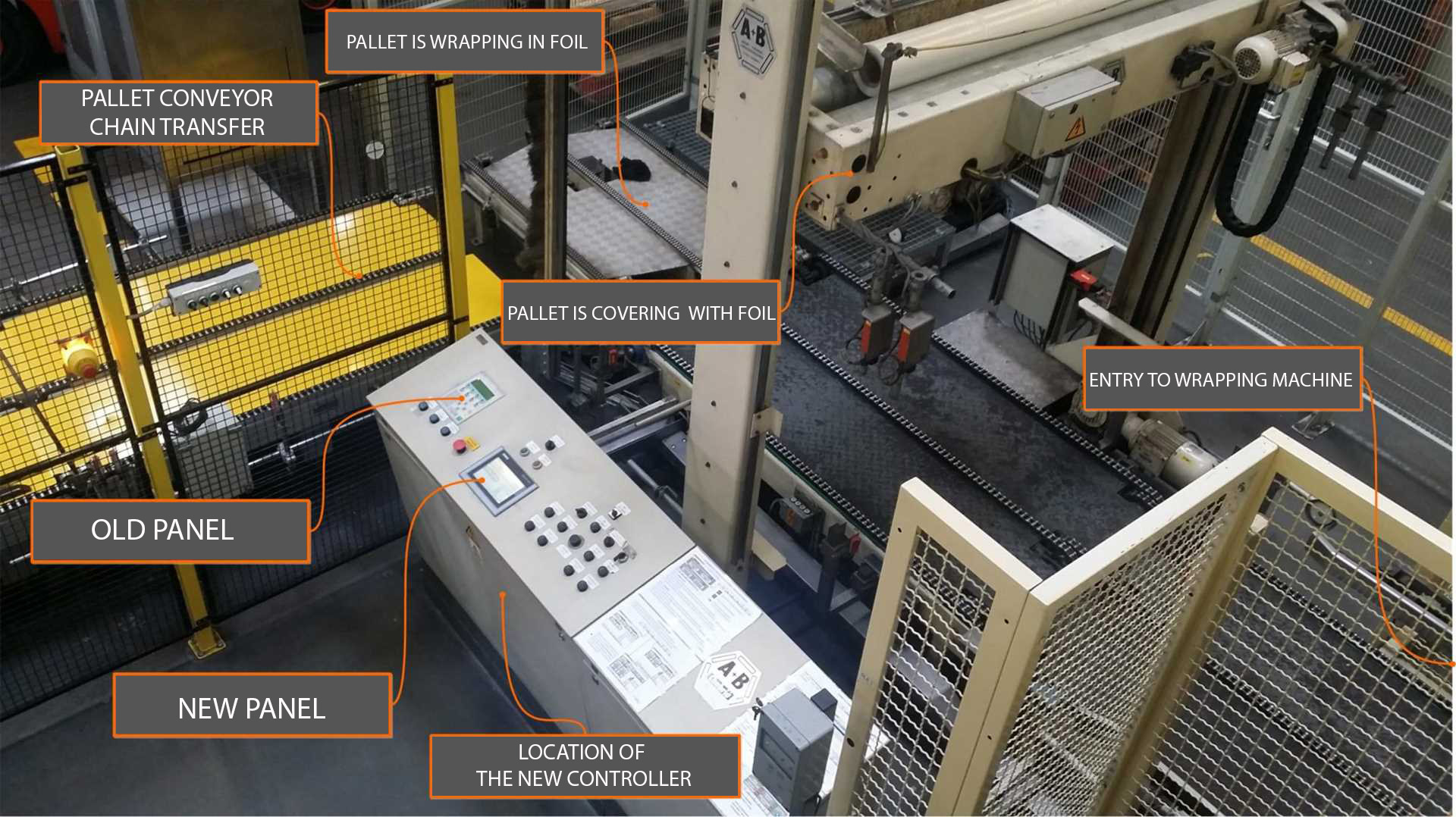
Siemens S5 controllers have been on the market since the late 1970s, today this equipment is being withdrawn and replaced by younger member from the Simatic family. This time it was the S5 controller’s turn, which controlled the pallet wrapping machine.
The goal of the whole modernization is the preventive replacement of the old PLC controller. The machine he controlled is in good condition, overall the S5 driver was also fine. However, if it breaks down, it is very difficult today for new CPU parts – input and output modules. In industrial plants, the line stoppage is very expensive and this point was like a ticking bomb. The old control system also had a lot of defects and poor diagnostics, which generated unnecessary losses. That is why there was a need to modernize this system.
Generally, this was my first major contact with the S5 controllers. I did not know them either from the technical side or from the side of programming. Initially, the solution to this problem discouraged me by the number of unknowns, but as I know, these are normal emotions when starting such projects. In this moment you have to break and just start working, collect the necessary contents one by one and identify unknown areas. The subject is self-developing and we are richer in new knowledge. I love this job 🙂
WHERE TO START?
Actually, this is a very good question! Where do we start the complex work? From the plan! With multithreaded tasks without any guidelines, not only we’ll be working in chaos but the effects will be rather measly. We start writing the plan from setting a goal or goals in the global dimension, in this case it looked like this:
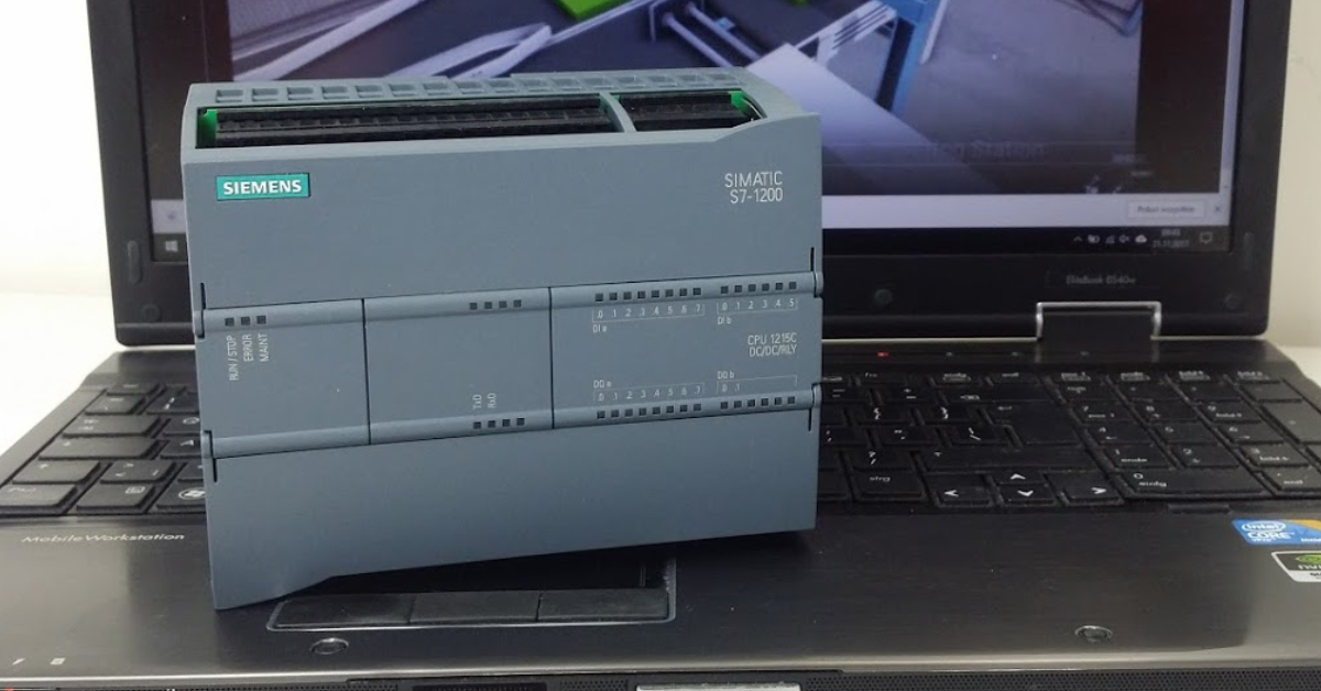
GOAL 1: Replacing the S5 CPU103 controller for S7-1200 1214C.
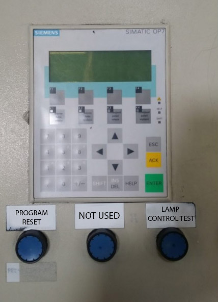
GOAL 2: Replacing the Simatic OP7 operator panel for the TP700 Comfort.
GOAL 3: Do not lead to stopping the production line.
GOAL 4: Implement the new control in use during continuous line operation.
The biggest challenge here was to face up to goal no.3. As we set the global goals, we can start preparing the list of sub-points for each goal. Subsections are issues and guidelines that we must overcome or fulfill to achieve the goal. So, let’s start:
GOAL 1: Replacing the S5 CPU103 controller for the S7-1200
- Concept for transferring the program from S5 to S7.
- Concepts for a new controller.
- Finding a space in control cabinet for two controllers.
- Understanding the functioning of the machine.
- Orderliness of I / O (inputs / outputs) of the new controller.
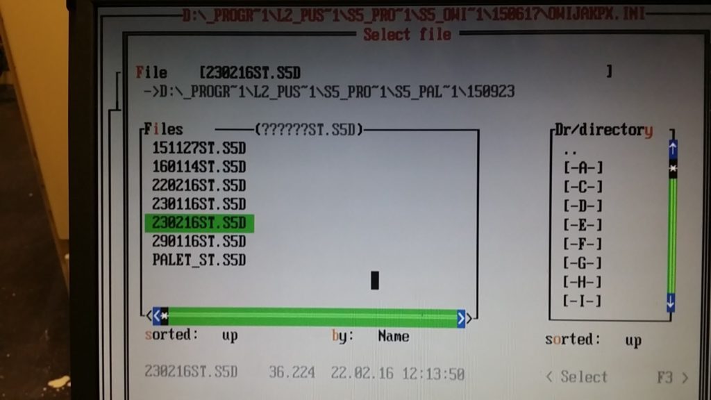
- Become proficient at the STEP 5 software that is supported by the DOS platform.
- Transferring the program to the Simatic S7 controller.
GOAL 2: Replacing the Simatic OP7 operator panel for the TP700 Comfort.
- Mastering the ProLite context for programming the old OP panels.
- Working out the dependencies between the OP panel and PLC S5.
- Developing the new HMI visualization on the TP700 panel preserving the character and the soul of the old panel.
GOAL 3: Do not lead to stop the production line.
- Develop a concept for efficient control switching between systems.
- Keep the possibility of returning to the old control system.
- Implement the new control in use during the continuous line operation.
You see? Even with such a general outline, it is much easier to start working. But only that. We can write a notebook in such a long-term operation, thanks to which we can easily recognize where we ended , for example when we have a stoppage in our work, for example a two-week stoppage. It happens.
CONCEPT FOR A NEW CONTROL

When selecting a new controller I choose the S7-1200 but for a while I took into account the S7-300. Both variants have their advantages and disadvantages, and of course I will introduce them to you immediately. Transferring the program from such an old controller is not that easy. Initially, I was looking for quick solutions, some automatic converters of STL code, because in this code was written program S5, for the standard S7-300 or S7-1200. There are some solutions for converting to the S7-300 level, however, as I have seen, they require many later corrections. The usage of this method also brings a lot of frustration due to the fact that we will not analyze the entire program. I had a lot of time to implement this project, so I decided to write the whole program from the beginning. Due to the huge difference in price, I choose the controller S7-1200 series in the following configuration:
- CPU: SIEMENS S7-1200 1214C DC/DC/RLY
- 2x UNIT 16 DIGITAL INPUTS: SIEMENS SM1221 DC
- 2x UNIT 16 INPUTS 16 DIGITAL OUTPUTS SIEMENS SM1223 DC/DC
My decision to write the code from the beginning had many benefits. I learned the old STEP5 environment – now I can do more such projects but also use it to diagnose and modify circuits on these controllers. The second issue is to analyze the entire program code from the beginning – it is a very good method to learn new solutions and concepts used by other engineers. The third advantage is the consolidation of programming art in the TiaPortal environment in which the latest Siemens controllers are managed.
CONPECT FOT CONTROL SWITCHING
How to implement a new PLC controller in the old control system to ensure an immediate switchover between the control of both systems? I had to learn a lot and seek inspirations from outside. I know that some automation specialists first communicate with each other two programmed controllers – old and new one, and in real time they change with each other the inputs and outputs of the controller and they are doing tests at the same time. As I found out (if not – correct me), this S5 controller does not have a simple option for communication with another controller, especially with the S7-1200. In general, you should not use such terms as “cannot” or “there is no way” in automation, because I have seen various miracles and combinations. However, when I felt frustration because of the long search for such a solution, I had to decide for something simple but functional.
I came up with an idea, maybe requiring a lot of work, but it had its advantages. Well, I decided to completely duplicate all inputs and outputs of the controller in total with the powering of all modules of both controllers. Switching the power was made with a simple switch on the desktop in a pair with several relays. All connections were made on one double-sided terminal strip.
This solution has provided me with the following comfort:
- Everything in control cabinet is in its place.
- I was switching the controller’s inputs and outputs on the terminal block during the machine’s micro-stops.
- I could switch the control between the S5 and S7 CPUs in real time.
- I was able to uninstall the S5 driver during working.
Such a solution had its drawbacks:
- There was a risk that somewhere in the routine of connections I would make a mistake (there is always such a risk).
- There was a risk that one of the wires would fall out of the clamp (because I clamped two without a double bush to save time).
- A lot of work related to wiring the old and new system.
UNDERSTADNING OF THE MACHINE’S FUNCTIONING
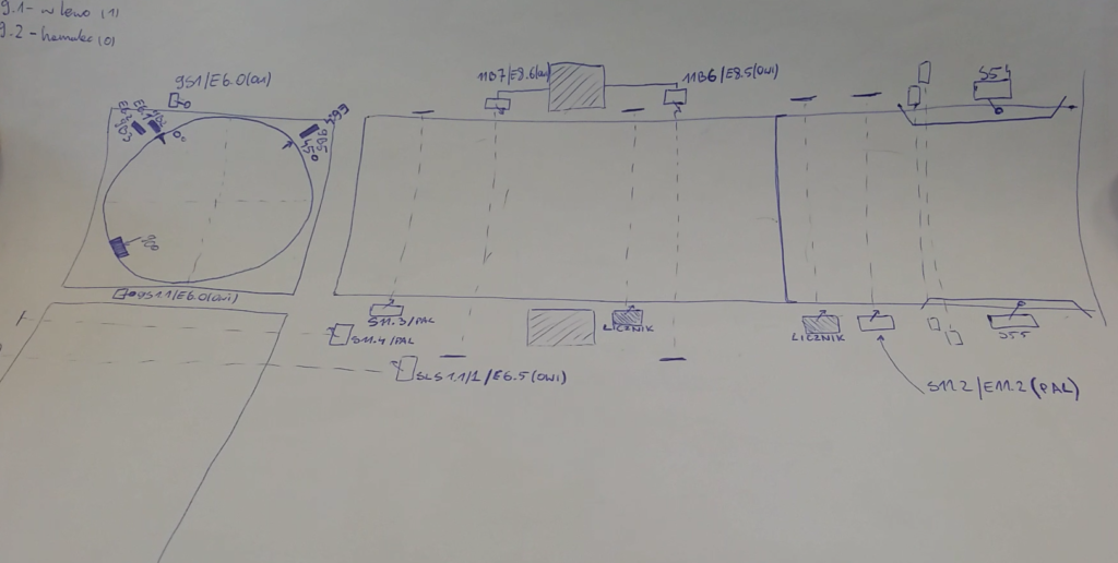
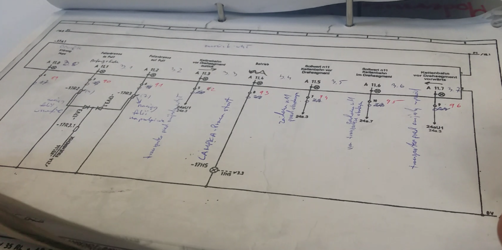
To rewrite the program I had to accurately analyze the whole control system. I had to do it with the help of my ring binder full of notes, because there where many issues to resolve (PLC program, HMI program, electrical scheme, dependencies with other machines). On the piece of paper I drew the machine from the hardware side with the indication of the most important elements of the control system, such as sensors, motors, etc. Regarding to the electric scheme, it was not only incomplete but also it was written in German. For what sins? I spent a lot of time before I familiarize with every detail if it.
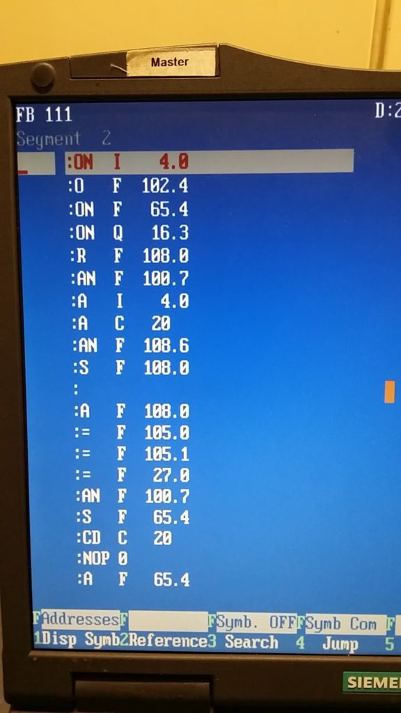
To learn something about the PLC program I had to do work to figure that out. Although the variables in the STL language of the old program were a little commented. But guess what? Commented in German. So… I took the smartphone in my hand + google translator and no German documentation scared me. Yeah… I wish. Sicherheits Abschaltung Andruckplatte oben or Höhenabtastung unten. Not only it’s so hard to pronounce it but I’s also really difficult to type it on keyboard. Now, I can confidently say that the old programmers should be respected for the coercion of programming under DOS, the massacre! I put a few pages of my notes down as a curiosity:
The STEP5 program has the option of generating the documentation, program structure and the entire cross reference of the PLC program. I printed the whole thing and then I’ve started analyzing the program step by step, writing down my comments and conclusions. At this stage I had to learn a little bit more from the programming concepts of these controllers. There are a lot of differences between old and today’s programs. Now I can say that the old programmers should be treated with respect for coercion of programming under DOS system, it’s massacre! Below I enclose some of my pages:
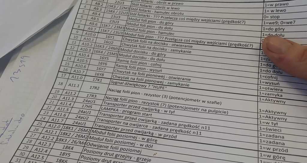
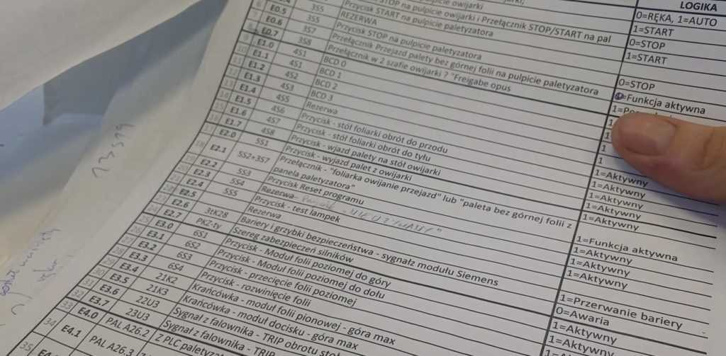
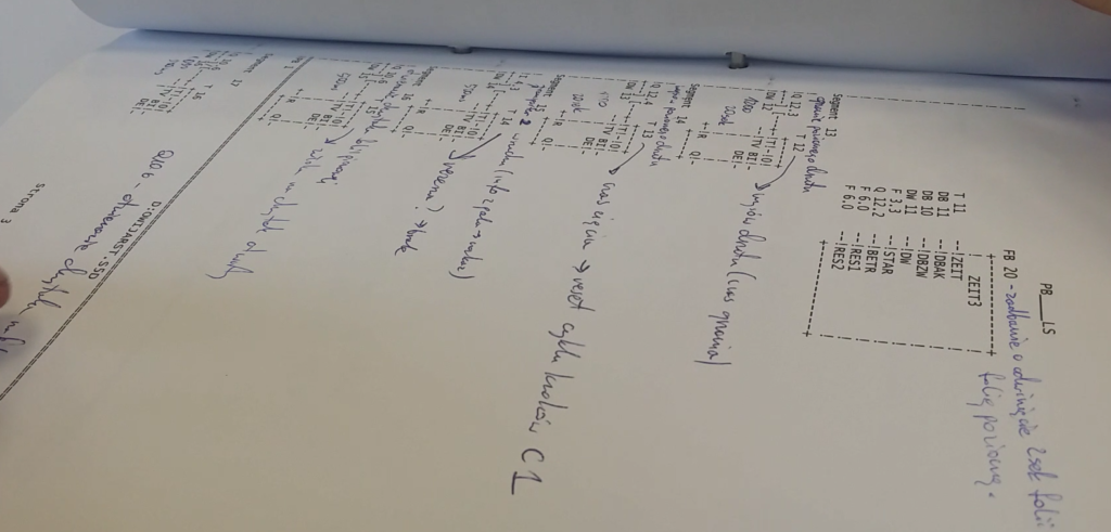
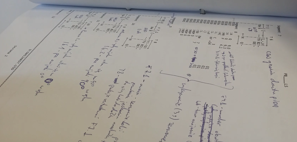
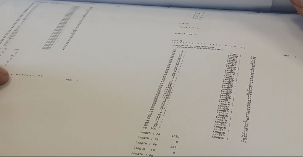
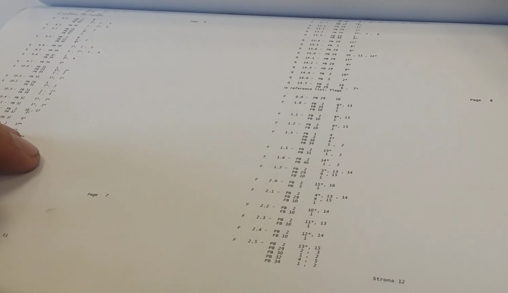

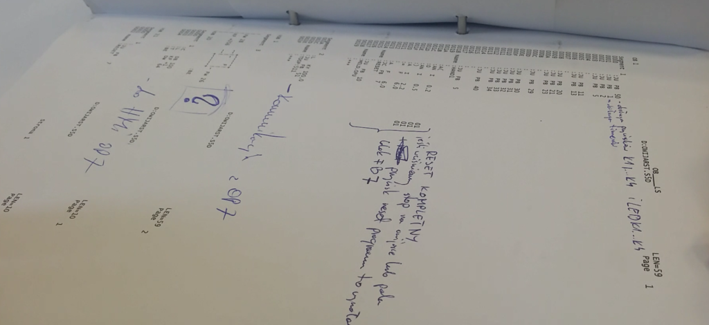

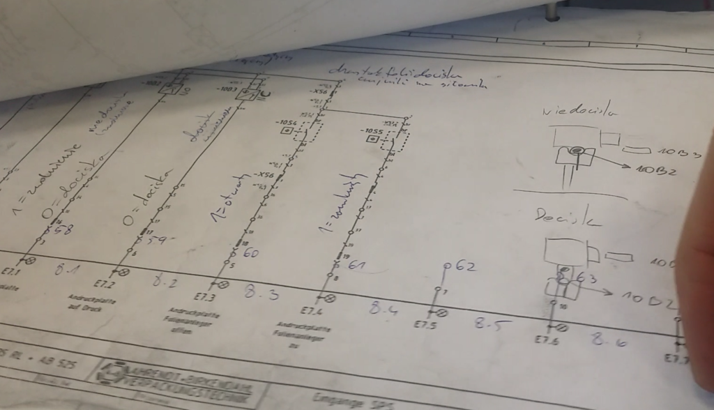

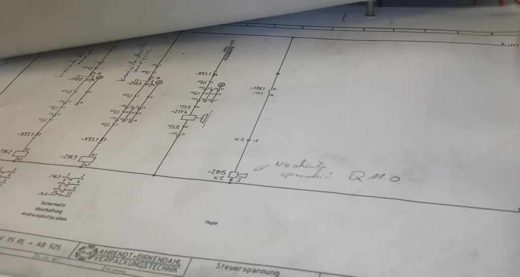
As you can see in these photos, not only I had to develop the concept of modernization, then, in the meantime, modernization of the modernization concept appeared. Scrawl, but even now I cannot imagine this realization differently. It is impossible to remember so many issues, in addition in German J It turned out to be a good idea to translate it and list all the controller’s inputs and outputs in the table. I used these pages from the very beginning to the end of this project. It was very helpful while writing a new PLC program.
Only when I realized that I know what I’m dealing with, I started to do modernization and programming work.
MODERNIZATION OF THE CONTROL CABINET
I started the assembly work from organizing the space in the electric cabinet. First, it was necessary to measure the dimensions of the new installation elements and then planning the modernization. To find enough place for a new controller and a strip of connectors, some elements had to be moved. Fortunately, I had enough wires and some of them had to be sewn up again. Additionally, the transformer was replaced for the decent Phoenix Contact power supply.
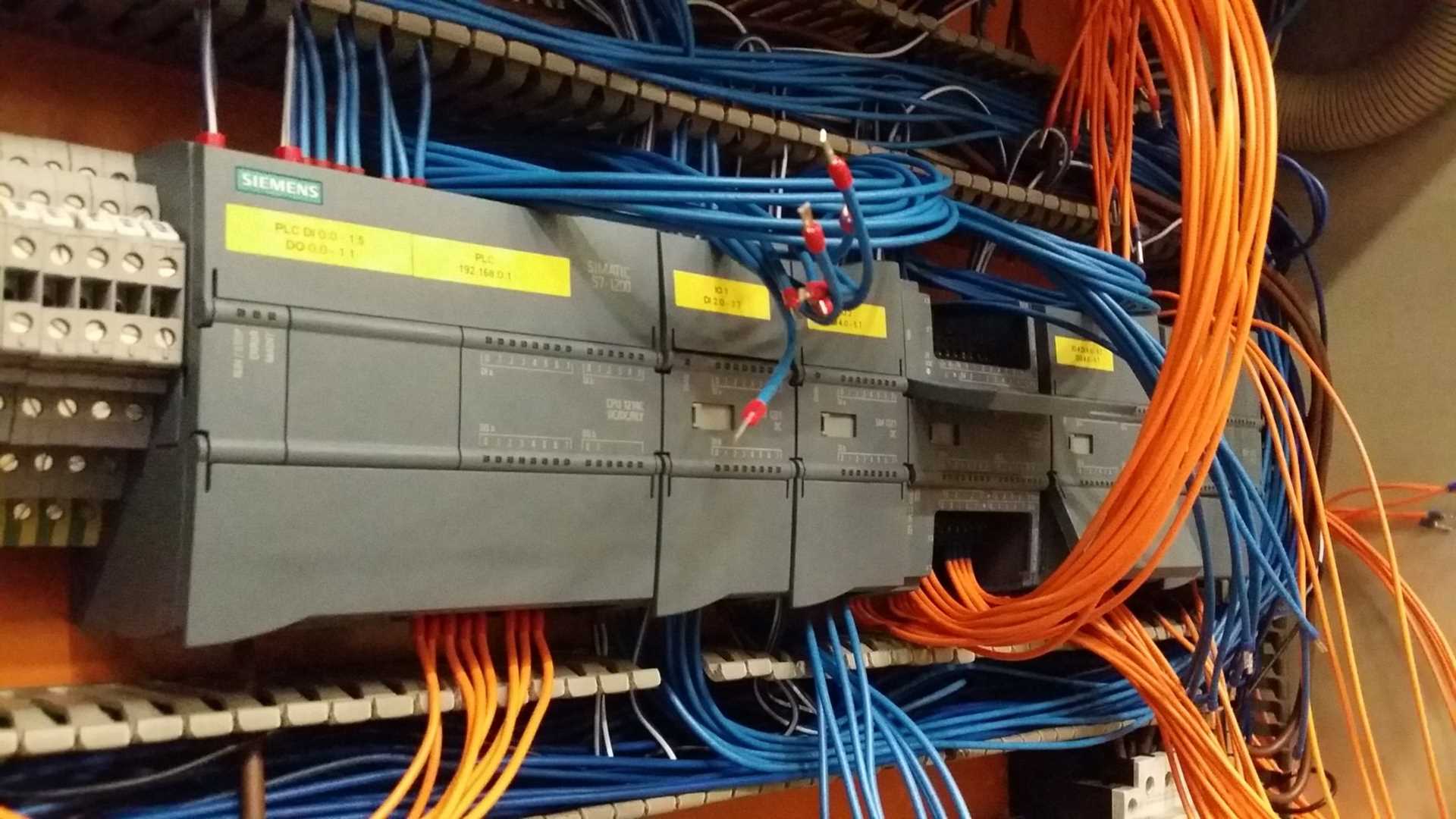
After installing the strips with terminal blocks (a total of 40 connectors x 3 tracks x 2 sides, so 240 terminals) and a PLC S7-1200 controller, I started to wiring the controller in a comprehensive way. So I prepared each wire that I was going to connect to this controller. Why in this way? Because if we have many thing to do, I’s worth doing them in one cycle. In this case I had to do, let’s say, 16 wires to one of the digital outputs modules. All of these wires were similar in length, so I could all 16 wires at the same time, clamp the bushing, with each wiring section. Otherwise, it would take me much more time.
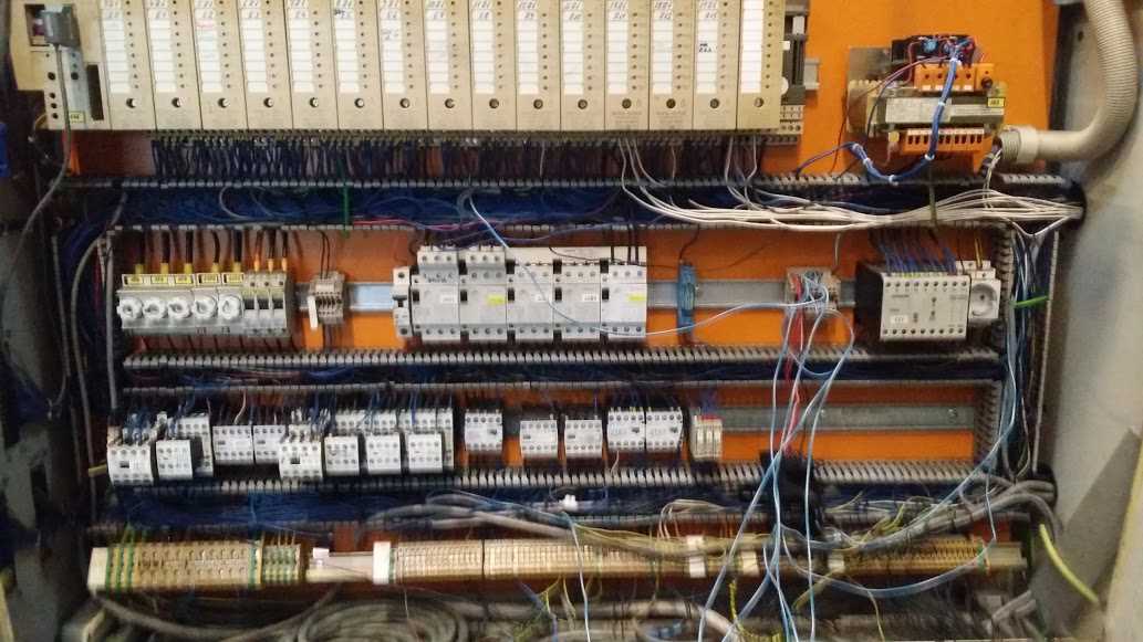
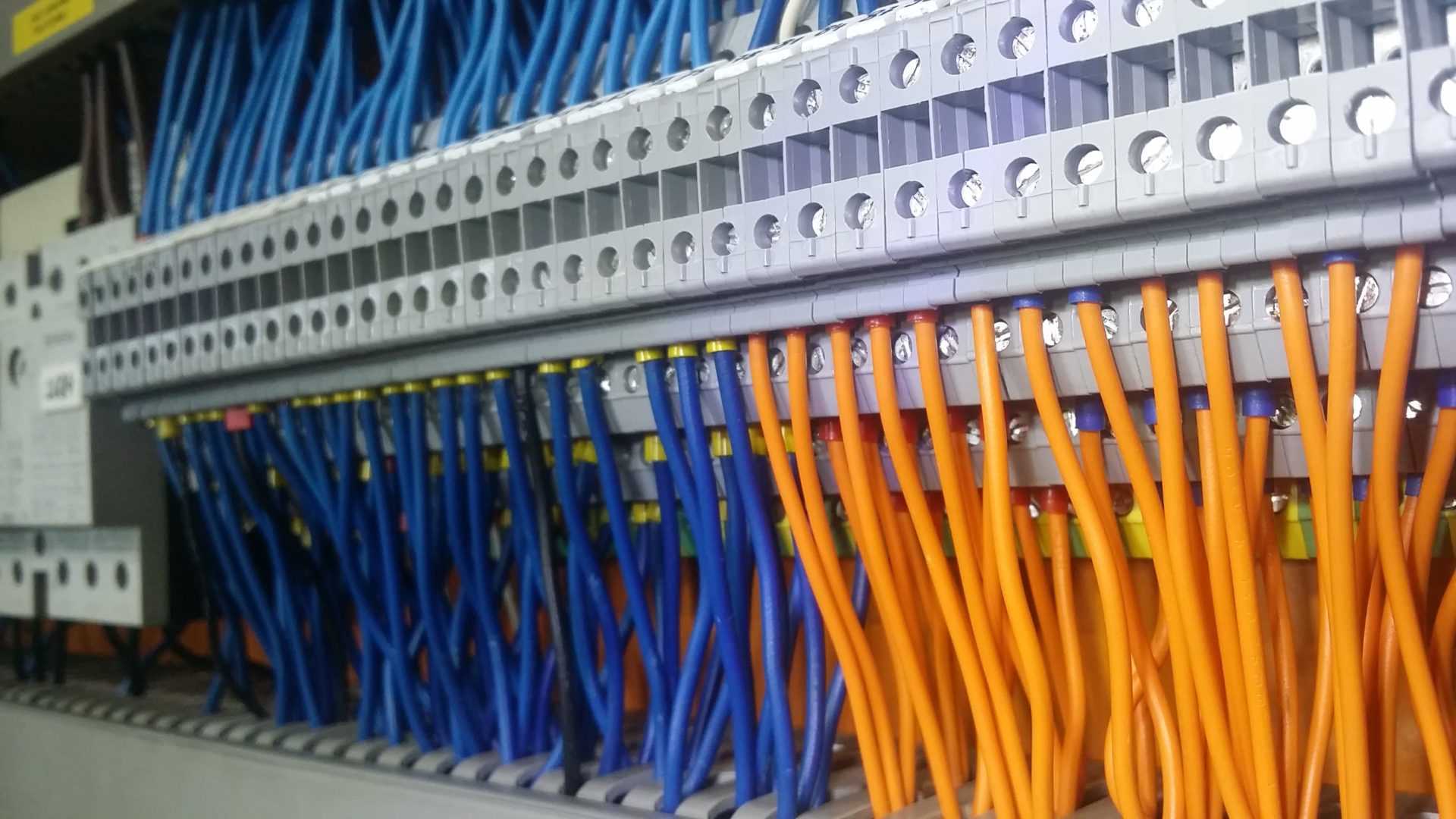
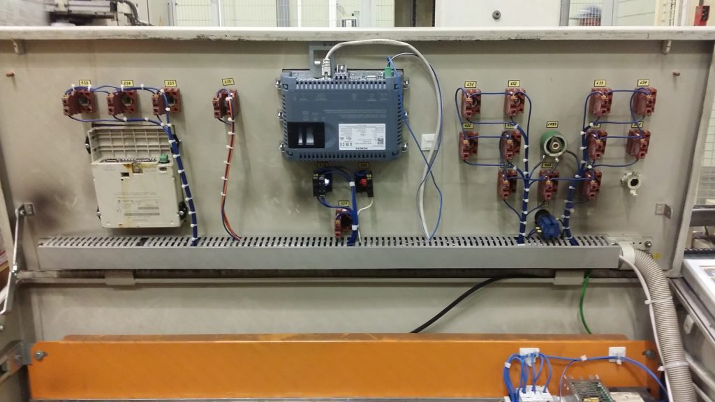
Finally I could start, lightly, but with some sort of caution, to duplicate all the connections of both controllers. As you can see the wires didn’t have any markings so even the small error could have cost me a lot of time.
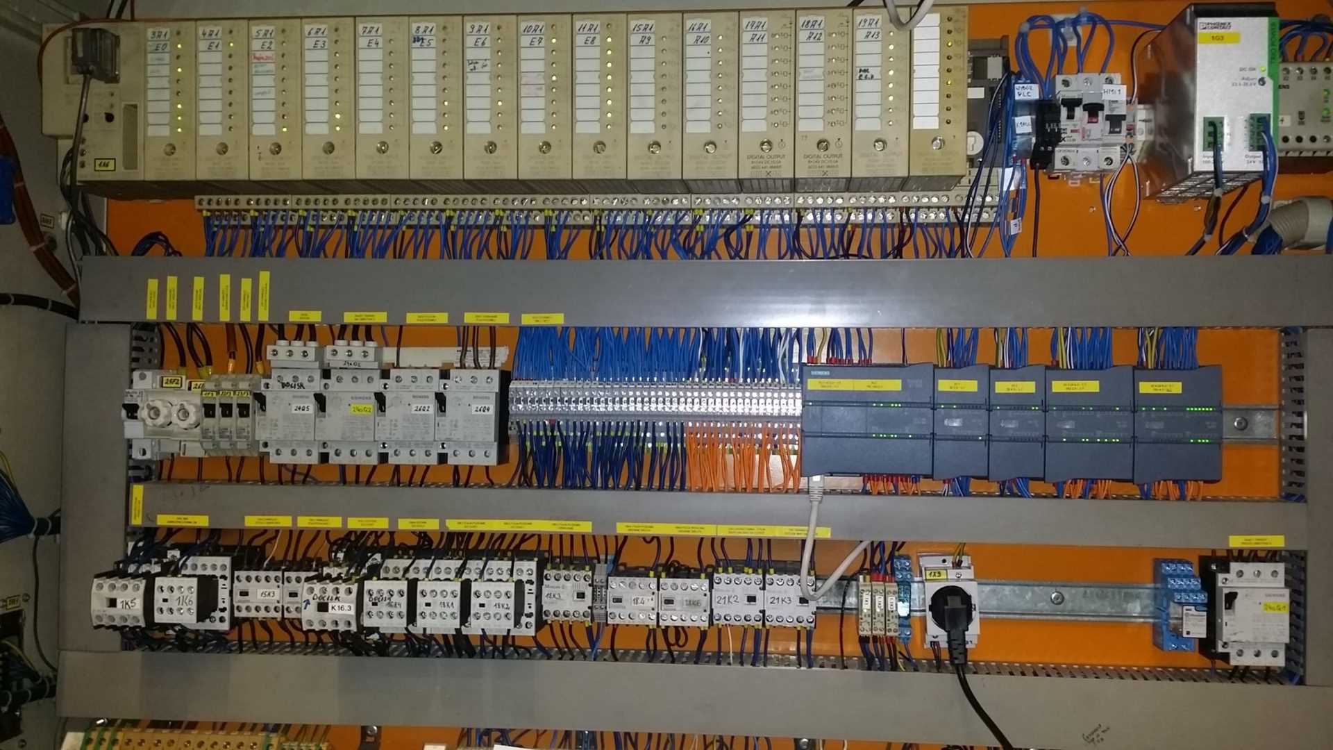
In the picture above, you can see in the middle a terminal strip. From the bottom, the blue wires are the connection to the external digital sensors, the orange ones are the outputs of the S7-1200 controller. From the left top – the blue ones are the connections of all digital inputs of both controllers. On the right there is connection od S5 controller outputs and control signals. In this case, this order seemed to me the most sensible, due to the length of the wires but also a subsequent analysis of connections – there is a certain analogy and it’s very important in the cabinets. When designing this method of connections, I took into account the subsequent disconnection of the S5 PLC, but about that in a moment.
At this point, you can certainly have some reservations to the orange color in the used outputs of the PLC S7-1200. I wanted to clearly separate these connections. Unfortunately, there was no other color on the state with the right contrast, so I took the orange one. Why this can be wrong? Because in industry orange wires are assumed to be signals or power circuits that can remain energized even when the cabinet is switched off. Otherwise: these wires are from external control system or fed by an external source. If I could start this project today, I would choose the blue color as the standards for all DC signals. This is not an unforgivable mistake because standards describe an orange wire for any use, but in this case it can be simply confusing.
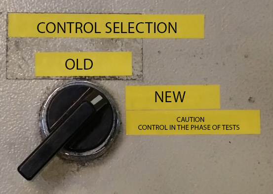
I haven’t described it yet, but at this stage the PLC program of the new controller was initially ready. Earlier, however, I will finish this thread. I used an unused switch on the control panel to switch the control between PLC. I just had to turn between the new and the old one and the relays in the cabinet properly switched the PLC power supply circuits, modules and digital outputs. As it turned out later, I did not use it for too long, but more about that later.
NEW PLC PROGRAM
With S7 controllers programmed in the TiaPortal environment, I had a contact before. Writing a new program was not extremely difficult because the wrapping machine is not really complicated. There is no a special process or value to adjust here. Digital control itself. However, due to the number of signals and many dependencies with other machines, the program grown to quite large sizes. I tried to keep the structure that was preserved in the old PLC program. It is not only about the input and output of the controller, but also about the bit memory and the organization of function blocks. I reduced the chance of a mistake in relation to some innovate method. Thanks to the fact that I started the program from scratch, I detected several errors in the program that potentially could posed a threat. For example, during wrapping the pallet with the finished product, it was possible to move this pallet during the table rotation despite automatic control. You had to press the manual control buttons in the right combination, but life taught me that such cases happen. You have to be sensitive for situations like this. As I mentioned earlier, the notes I did during the layout analysis, were very helpful when writing the whole program. I made a table with all the inputs and outputs of the PLC with the description from which devise they came from. Additionally I added the logic of the digital signal. Thanks that, I didn’t have to search one of the 120 signals among the S5 or S7 programs. Just one glimpse at the table and I could go forward with it.
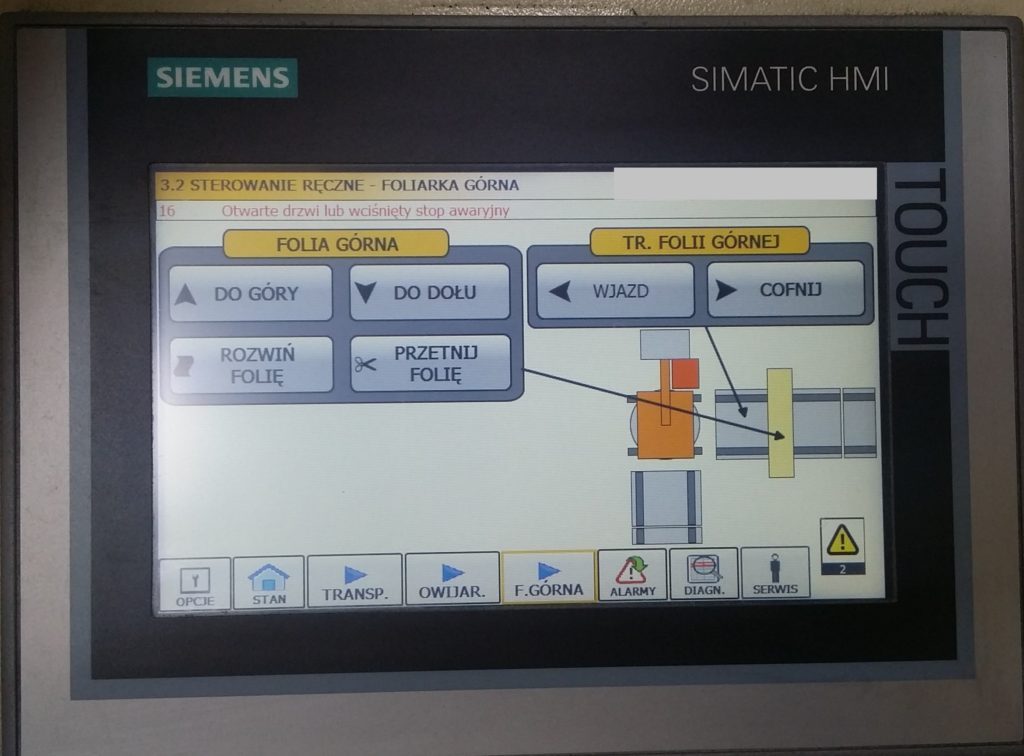
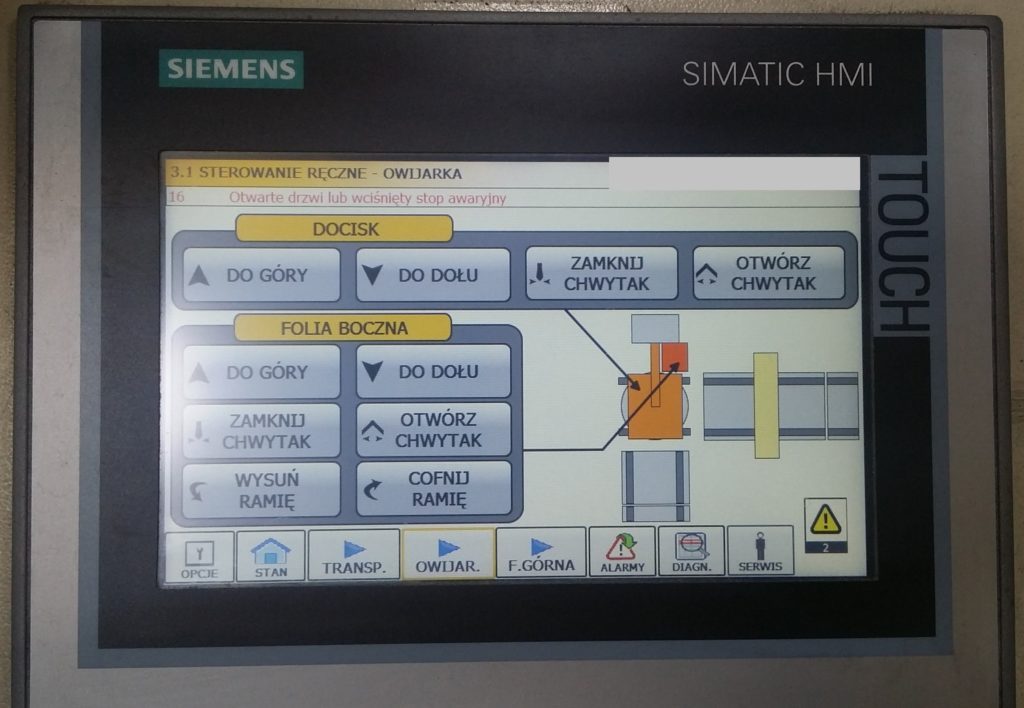
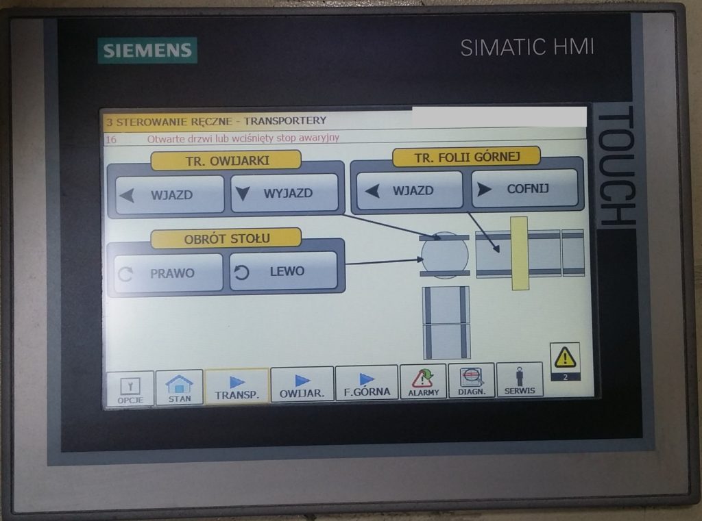
NEW TOUCH PANEL TP 700 COMFORT
If someone just asked why this panel, it’s just because there are several similar panel models in this plant. From the perspective of keeping the flow, this is very important because it works forward to standardize and optimize the inventory.
The OP7 Panel left a lot to be desired. Not only he offered the text for display, it also contained the small amount of diagnostic functions. There were also no settings for the machine’s operation parameters. It was always required to connect to the programmer to change some parameters.
I like operating panels for programming as much as programming PLC controllers. It takes a lot of patience to do an aesthetic and functional application for the operator. Well, I have this patience J When building an application for operator panels, I am guided mainly by the principle that if the operator achieves the desired effect by maximum of 3 clicks – then the application is good. Of course, it’s not always possible but in my opinion the service should be simple and intuitive. This is great material for writing a separate article. I already have a plan for it: How to do a good visualization for HMI operator panels. Do you guys want a topic like that?

At the beginning there were no place for a new panel on the control desk. I just had to move the safety button and cut out the hole. Sparks, file, fastenings and the panel it’s on the new spot.
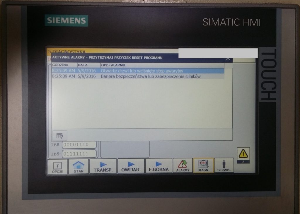
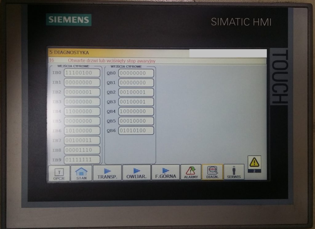
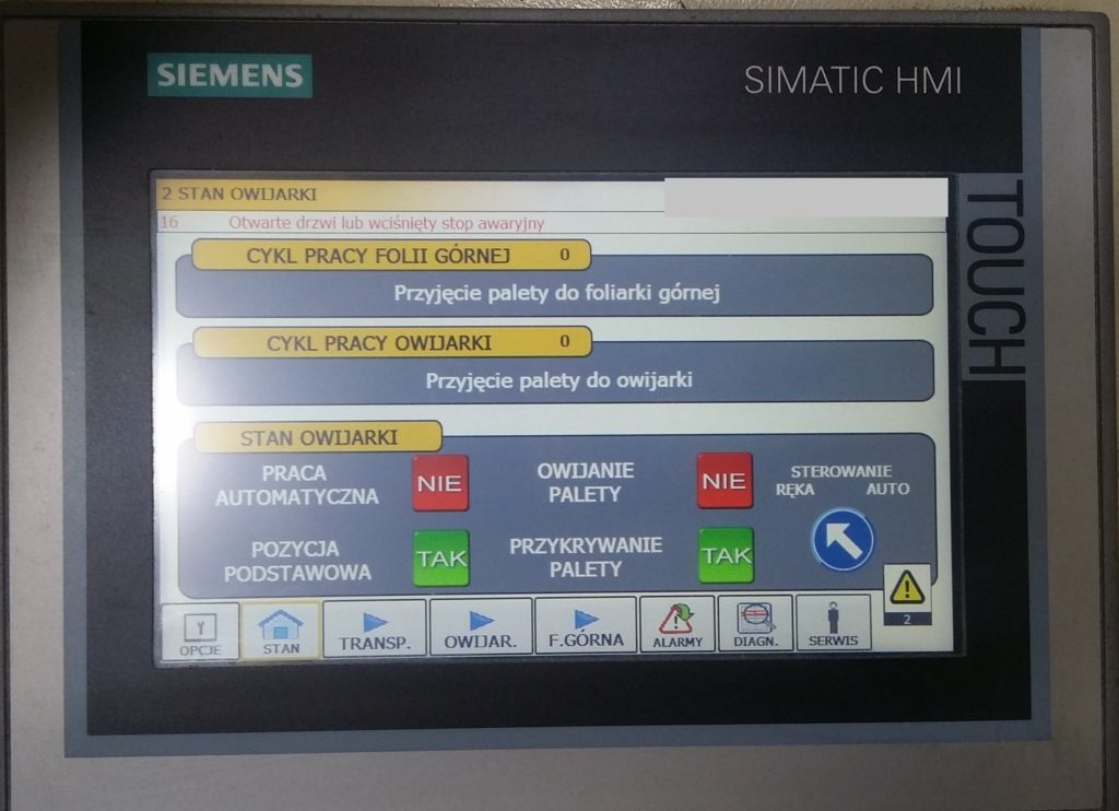
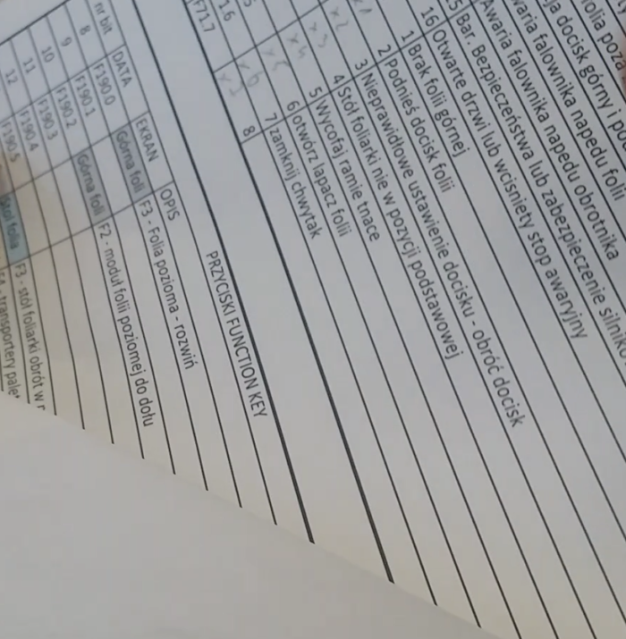
The new applications has been enriched by the entire list of alarms (with archiving) that appear in the case of defect. Previously, the machine was able to stop add there was no message on the panel. There were also possibilities to change the settings via service screens (times, speed or number of revolutions).
The entire application for the operator’s panel has been armed with the POKA Yoke method, that means automatic responses and ways to avoid accidental errors. Generally speaking – idiot-resistant method. For example, you can use poka yoke in the car. When you leave the car and you don’t turn the lights off, you hear the beep sound. Here, when you want to start machine in auto mode (after restarting the work cycles) you have to set up the moving elements into the start position. Poka yoke which I used were automatic hints – flashing red dots on buttons that should be used in manual control mode. As you activate the button, the flashing icon automatically disappears from the button. It turned out to be quite practical method.
TESTS OF THE NEW CONTROL SYSTEM
Now it’s the time to start-up the new control system. Adrenaline and emotions were in abundance. The line is working, the pallets are moving and the wrapping machine is spinning. I blocked the entry for pallets into the wrapping machine, waited until the forklift operator picked up all the pallets and… I turned the control mode selection switch to NEW! I unblocked the entry for pallets into the modernized machine and I’m waiting. The pallet has moved, it’s under the covering with foil… it’s working like a dream. First success! The pallet is already covered with foil. Now it’s time for the resistance wire to come out to cut the foil and the part of the cycle is behind us. The wire cuts through the foil and the pallets move on. I thought, it can’t be so beautiful, probably something will screw up in a minute. The pallets starts to enter the rotary table of the wrapping machine. I prayed for the pallet to not go any further and stop at the end of the table. Woo… the entire cycle of entry to the wrapping machine pre-finished with success. The press is pulled down and pressing the pallet and the cycle of wrapping begins. There are many stages and it’s very likely to make a mistake. But no! the table is spinning and the pallet is wrapped in subsequent layers of foil 🙂 I couldn’t believe my eyes. The end of the wrapping cycle. The table begins to set up with chains to leave for pickups, it stops and…? The pallet remains in the same place but I should go away. Hey, it’s not that bad. The whole process was monitored on the S7-1200 controller online preview, so after analyzing this part of the program I’ve quite quickly found the reason – not this bit and not right here – standard:(. Amendment, download and it finally went through. The pallet went for pickups, then the next pallet, and the next and the next… Wonderful!
Almost wonderful! Later I spent the whole day testing all functions of this system in both manual and automatic mode. I tried to generate as many cases of abnormal functioning as possible. Unfortunately, not everything went as I planned. There were some minor mistakes. On the panel, the register was badly connected to the object. The bits weren’t on the right place in the PLC program. I corrected as much as I could and I came back to control the old system, because I didn’t want the machine to work without my supervision. And at this moment the problem showed up.
DO YOU HAVE SIMATIC SIEMENS S5 CONTROLLER? GO AND BUY A BATTERY.
Do you already know what’s going on? After switching to the old control mode, the machine stands like nothing ever happened. There is only a message on the old panel about the lack of commutation with the PLC controller. What the hell? I check the cable connection between HMI and PLC – it looks good. Diagnosing and looking for a reason takes too long, the line is standing, so I return to the new control. It works perfectly fine.
I decided to “briefly” connect the PLC S5 to the power supply to diagnose it with the old PG programmer in STEP5. I connected the wires and went online. STEP5 sees the controller, so it’s not that bad. BUT! There is the lack of any program in the controller. It turned out that the battery supporting the controller’s memory had run out. It is not a regular battery but a special one with non-standard dimensions and voltage of 3.7 volts.
Do you have a S5 controller working on a different object? Check the battery voltage. If it’s necessary, replace it on the controller connected to the voltage and have one in stock. When the battery runs out, the program from the controller will be gone forever. Do not forget to make the copy of the PLC program.
In this case I had a copy, so I was able to restore the program. However, the management decides that if the machine works efficiently on a new system, it should not be disturbed. At most, there will be a rescue operation. Fortunately, it was not necessary J It is very rare that the program stars working without any corrections. this time I was very close.
TRANSFERRING THE SYSTEM TO USE
I was thinking about the best form of operator training. It’s not easy to gather everyone together in one group. In my career I had many groups for training. From experience I know that in the group of 10 people, only 2-3 are listening. The rest of them have an approach like “it doesn’t concern me” or “I just work here”. It could be a little different here, because everyone wanted to be able to operate the new TR700 touch panel.
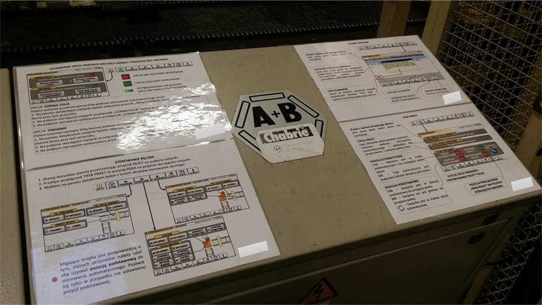
In fact, the application on this panel was so simple and intuitive, that every single person that came by, knew immediately what and how to do it. I came up with an idea that I could prepare a short user manual and I will place it directly on the operators desktop. I initially implemented two people which gave the information further. Subsequent completed the knowledge from the lesson placed on the desktop. The idea went well and I had the opportunity to teach people advanced functions, as often as I could.
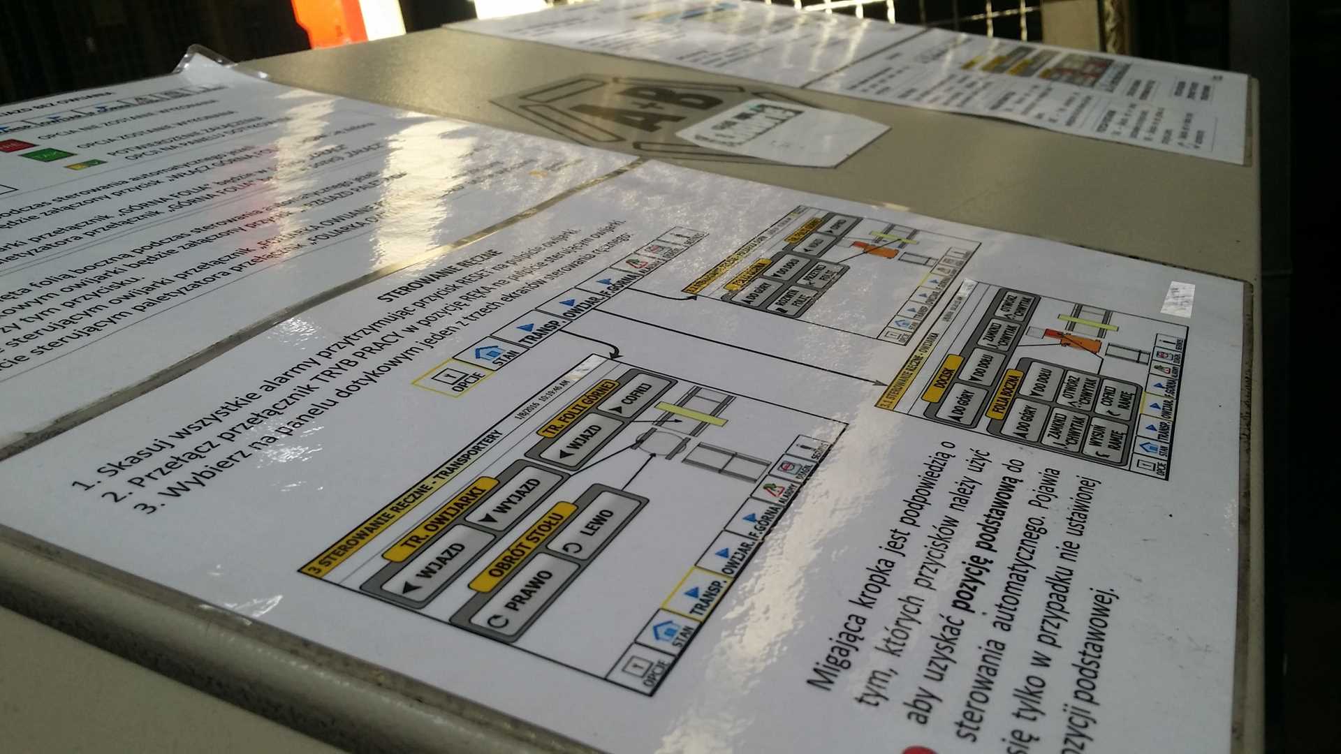
I’ve made the whole user manual in my favorite program, which is ideal for such applications. It’s called Microsoft Visio. The program is used to create diagrams, charts, menu structures, user manuals etc. Visio can seamlessly integrate with other graphic programs and the entire MS Office package. Personally, I save a lot of time during creating drawing and diagrams.
THE END OF MODERNIZATION WORKS
The whole program worked several weeks before I decided to dismantle the old controller. The new layout has been so though through that this stage ran smoothly. I just had to remove the wires from the installed strip, which were connected to the Siemens S5 controller. Later I just had to loosen a few screws and dismantle the old driver. The effects can be seen in the pictures below:


SUMMARY
Although it took me a hell of a time to realize this topic, I am glad that I had the opportunity to face it. In this way I proved, not only to myself, that automation specialist can handle the unknown. I have expanded my horizons with new experiences and opportunities. Since that time, the control system had passed a lot of subsequent changes. including enrichment of the PROFINET communication network with other machines and it’s doing great today 🙂