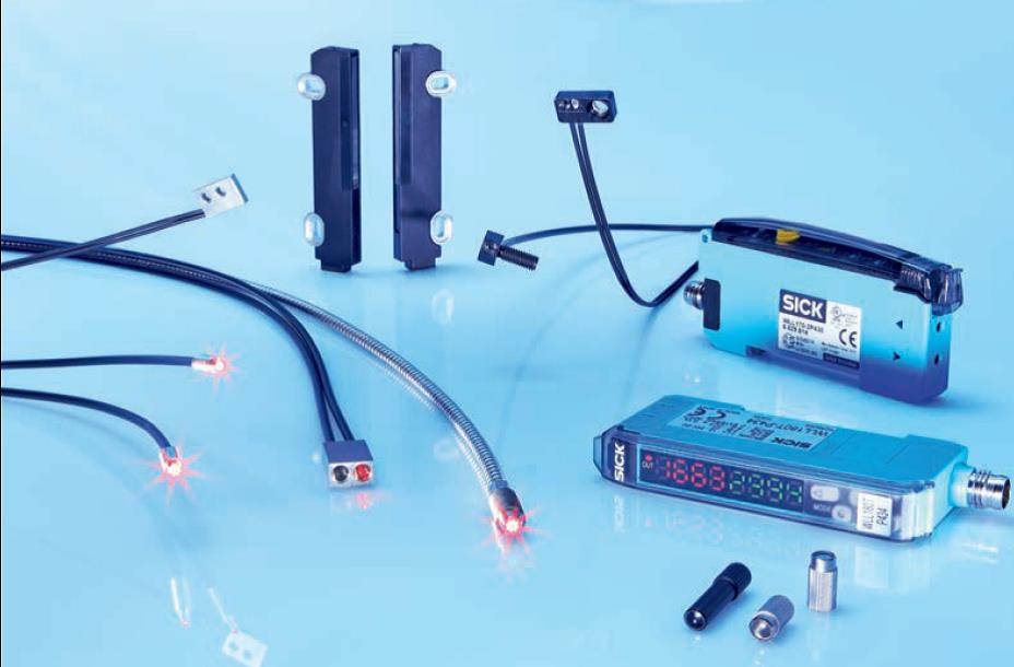
Nowadays, systems of industrial automation require intelligent detecting of objects. No matter how complicated are the requires, properly selected photoelectric sensors are reliable solutions for many applications, in which we have to deal with different challenges. Photoelectric sensors increase the efficiency of machines, affect the increasing of quality of production, minimize the risk of shutdowns, increase the energy saving, etc.
This article was created in cooperation of few people. We tried to show a wide look of the most commonly used photoelectric sensors in the general sense and application, which makes the article very long. Therefore, Dear Readers, do not treat this article as “for once”. Nevertheless, the information contained here is worth assimilating as an arsenal of automation specialist knowledge. We also recommend this article for everyone who has to deal with machines containing photoelectric sensors.
More detailed discussions for selected groups will be presented in the next parts of the series of photoelectric sensors.
Basic parameters of photoelectric sensors
Some of the parameters of photoelectric sensors depend on the type of photoelectric sensor. Generally, you can distinguish:
- Range of operation: maximum and / or recommended (under typical industrial conditions) or reading range / focal length.
- Accuracy – if photoelectric sensor has an analogue output or network interface, the accuracy is usually given, i.e. the value (relative or absolute), which is the difference between measured and actual value.
- Resolution – it is given in the same way as for the cases above. Resolution is the smallest measurement step.
- Repeatability – generally, it is given in more precise photoelectric sensors, e.g. for accurate measurements of distance, dimension of elements, their thickness, etc. Repeatability determines the compatibility of measurements results of the same value, assuming that the measurements are carried out using the same photoelectric sensor.
- Type of electric output – switching/digital, analog, relay.
- Function of photoelectric sensor output – Light ON or Dark ON. This point will be discussed in the further part of this article.
- Power supply
- Electrical protection class from the point of view of fire protection. Most often it is class II or III. When marking the protection class of photoelectric sensors there are some references – it is worth knowing.
- Layouts protecting the photoelectric sensors electronics – for example: A – protection of photoelectric sensor electrics by changing the power poles, C – suppression of interfering pulses during connecting the photoelectric sensor power supply (for the start-up time the photoelectric sensor cannot give a false signal), D – output protected against overcurrent and short-circuits.
- IP (International Protection Rating) – it is about the resistance of the photoelectric sensor to dustiness (first digit) and moisture/water (second digit). Typical IP are IP66, IP67, IP69K. Very often they are given together in documentation considering one sensor. It means that the photoelectric sensor meets the condition for different degrees of protection. Important! The higher protection level number does not always mean that a given photoelectric sensor with a higher “number” is better than the one with the lower one. This means that the photoelectric sensor was tested in a different way and has been classified/fulfill the conditions for the given IP. The inquisitive people can check what, for example, the IP66, IP67, IP68, IP69K norms concern and how the testing procedures (static and dynamic) are running.
- Range of operating and storage temperature – this part does not need to be discussed. It is worth mentioning that depending on the purpose, the values of operating and storage temperature ranges may differ in the same sensor (photoelectric sensor with installed heating, with extender operating temperature range, etc.). The general distribution of photoelectric sensors is shown below. In particular groups, there is also a detailed division, e.g. due to the technologies used and/or application.
Outputs of photoelectrical sensors
Switching/digital, analog, relay outputs.
The switching/digital output is usually implemented physically as PNP or NPN transistor outputs. They are used in the case of quick tasks, when quick response time is important, the signal from the photoelectrical sensor is brought to the PLC or card input and the photoelectric sensor “does not supply” another device from its output. The advantage of this outputs is the high switching frequency/minimum response time to observed object. The disadvantage is the limited possibility of loading the output by the external system of the machine/device.
There are also versions with PUSH/PULL, MOSFET semiconductor outputs and with symistor on the output.
The second most common type of photoelectric sensor output is the relay output. The advantage of this output is possibility of powering the device directly, which is to be controlled by a photoelectric sensor. Power supply to the device can be provided from the same source as the power supply of the photoelectric sensor or from another source (this should be check beforehand!). A part of the photoelectric sensor with relay output has a galvanic separation of the opto-electronic layout from the relay. It makes possible to supply the opto-electronic layout with one type of power supply (e.g. DC voltage) and the relay layout with another (e.g. alternating one), if required. Thank to which, for example, when the object is detected, the photoelectric sensor will start the device (or part of the system) by supplying power to it. The disadvantage of relays is their lower switching frequency (resulting from relay construction), worse response time and the ability to sintering of contacts in the case of high current flow for a long time. The relay can also be overloaded mechanically – it will fall apart after certain period of time with excessive use / forcing too high frequency of switching over a long period of time.
Functions of photoelectric sensor output
For some versions of photoelectric sensors, it is difficult to use NO/NC terms. This is associated with a more difficult interpretation, for example in the case of photoelectric retro-reflective sensors or through-beam photoelectric sensors. For the needs of photoelectric sensors, the terms “Light ON” and “Dark ON” (also called “Light OFF”) were created. There are also slightly different variations of this naming method. In general, it is about the principle of issuing a high signal at the output and its interpretation in the case of receiving light by photosensitive element of the photoelectric sensor (Light ON) or no light (Dark ON or Light OFF). The transmitter of the photoelectric sensor emits a modulated light beam.
- Light ON – if the light from the transmitter got to the receiver and on the photoelectric sensor output we have high state, then we say about the logic “Light ON”.
- Dark ON – if the light from the transmitter did not get to the receiver and on the output we have high state, then we say about the logic “Dark ON”.
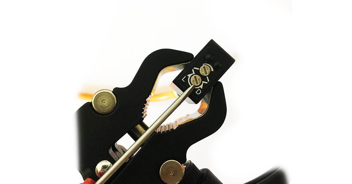
Photoelectric sensor with one output. You can see here the potentiometer for changing the Light ON or Dark ON output function.
This way of thinking makes easier the understanding of the photoelectric sensor logic, no matter if this is, for example, photoelectric retro-reflective sensor (operating with reflector) or through-beam photoelectric sensor. In the case of describing the output functions, their interpretation is simple when we have to deal with photoelectric sensors with one output (typical marking of output is “Q”). In the case of more than one switching output, in photoelectric sensor it comes to wrong interpretations.
To be sure, the “Light ON” and “Dark ON” output function will be presented separately under the further discussed photoelectric proximity, retro-reflective and through-beam sensors.
Below is an example for photoelectric proximity sensor for output with PNP and NPN polarization. You can see Q and /Q output.
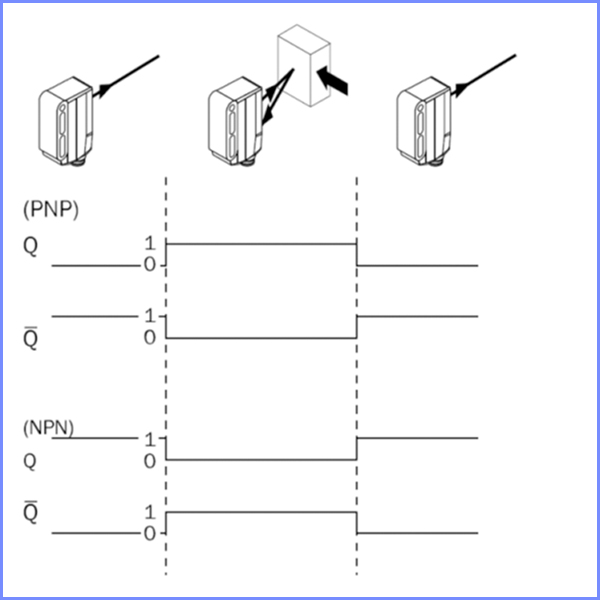
Proximity version 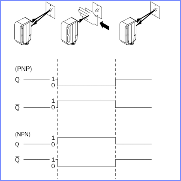
Retro-reflective version 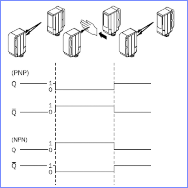
Through-beam version
As you can see, there are some differences 🙂
Photoelectric sensors are also build (especially the cheapest ones) with the output function allocated for good. Then we have to be sure if we choose the photoelectric sensor with Light ON or Dark ON function.
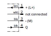
Example of photoelectric sensor with one Q output. Pin 2 is marked as not connected.
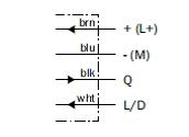
It’s not the end of the story. There are versions of photoelectric sensors with one output, which function is determined by changing the position of potentiometer on the photoelectric sensor body. Some of the photoelectric sensors – especially models in cylindrical bodies – have a version with an additional wire used to change the output function. Depending on which output function we want to use, the wire marked as L/D is connected to the + or – of the power supply.
Power supply of photoelectric sensors
In photoelectric sensors with transistor outputs, the most common type and power supply range is 10 … 30 VDC. The most commonly used are 24 VDC stabilized/pulse power supplies. With more complex photoelectric sensors, the DC power supply changes and amounts to 18 … 30 VDC. These constructions also take more electricity needed for their proper operation. If someone likes to use battery-powered testers for such photoelectric sensors, after a few minutes someone may be very surprised with the battery status.
Photoelectric sensors with relay output usually work as DC and AC versions. However, each time it should be checked because there are exceptions to the rule. Typical voltage ranges for these constructions are 12 … 24 VDC and/or 24 … 240 VDC.
You should also pay attention to the maximum output current (load) in photoelectric sensors with transistor output (in the case of overloading the transistor, you can burn the output of photoelectric sensor) or the maximum switch current (switching voltage) of the photoelectric sensor with a relay. The typical maximum value of load current in photoelectric sensors with transistor output is 100mA, and the typical value of the peak current for photoelectric sensor is 3 … 4A for 24 VDC or VAC, however, it cannot be longer (relay contacts sinter).
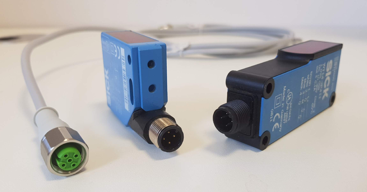
Typical connection of sensors
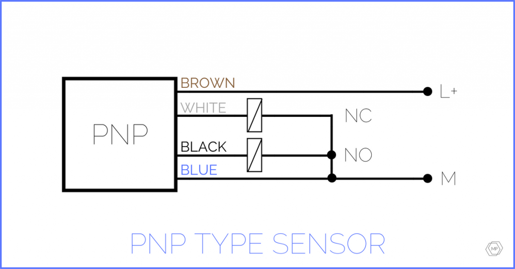
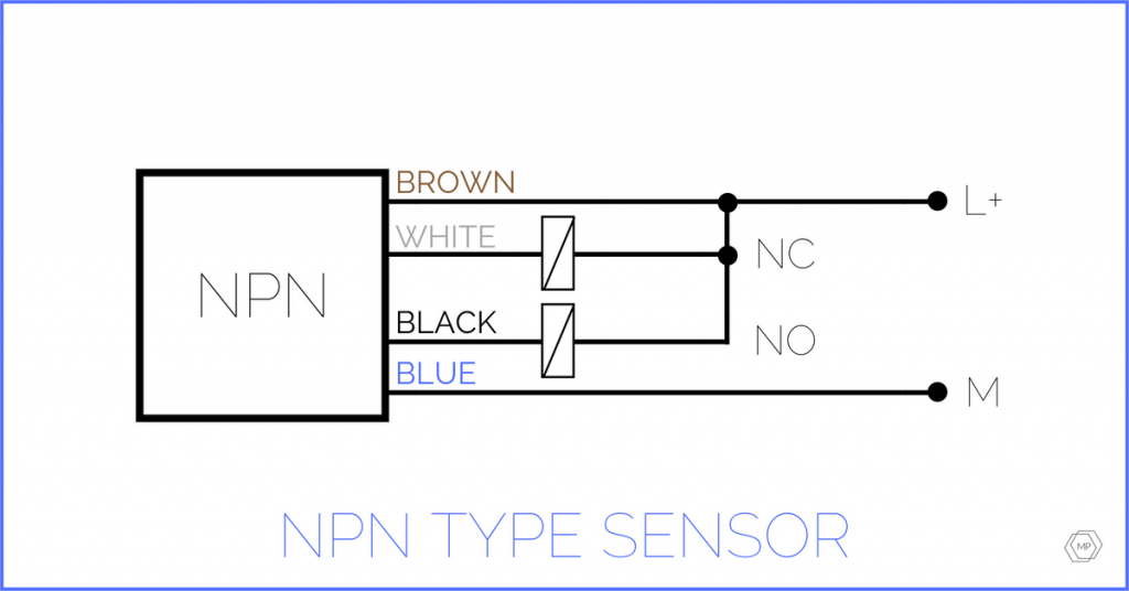
The most commonly used type of connection in photoelectric sensors (drawing below) is 4 pole M12 plug, where sensor outputs and power supply voltage contacts are usually connected in the same way, and signals have the same colors of cables. However, this is not the rule!
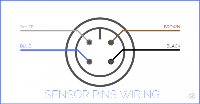
- Brown = L+
- White = /Q
- Blue = M
- Black = Q
KEEP VILIGANCE!
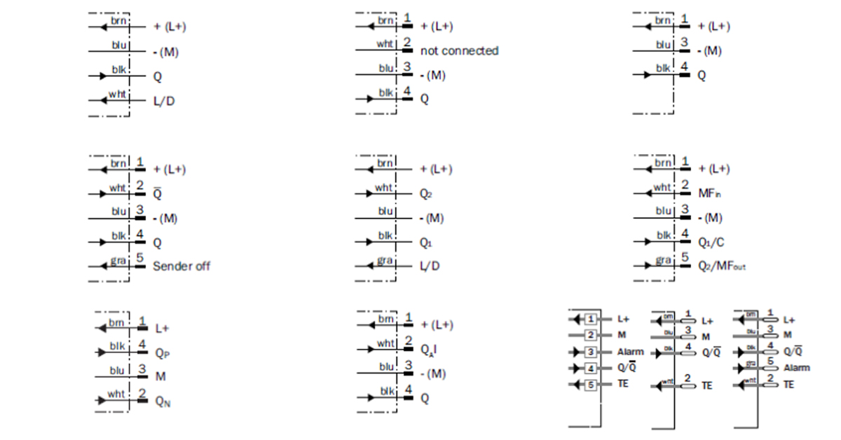
In the case of electric connection of photoelectric sensors pay attention to the symbols on electrical schemes. While in the case of photoelectric sensors with M8 connector there are typically 3 and 4 wire versions and with M12 connectors typically 4 and 5 wire versions, there are also M12,8 pin and Q6,Q7. The markings of the sockets in the case of M12,8 pin depend on the number, type of outputs or transmission from the sensor (if the sensor works after some protocol/network). Wires with M12,8 pin plugs have several coloristic types veins. If you choose a wire with M12,8 pin plug with the wrong color for the photoelectric sensor without electronic protection, it may cause its damage.
The sensors with 4-wire M8 and M12 sockets can also have different connections. While the veins/pins correspond to the power supply (usually 1 and 3) and the 4 for typical Q signal, then 2 can be /Q (i.e. Q output negation), unused (usually named in documentation as “not connected”) can be used for change of the output function (the mentioned above L/D wire), as a universal MF connection (so-called multifunction), which we programmatically define as output, input (e.g. for remote programming of a photoelectric sensor from the level of desktop button), as an input disabling e.g. a transmitter of photoelectric sensor (photoelectric sensor test function). There are also photoelectric sensors communicating on various protocols, e.g. IO-Link or photoelectric sensors, which have one or more outputs and each of them can be programmed on the different distance. Photoelectric sensors with several programmable outputs at different distance have Q outputs marked with consecutive numbers, e.g. O1, O2, O3. The change of the output function usually takes place jointly for all outputs.
The output operating after IO-Link protocol is usually marked as “C” or Q/C. Such output is usually made as the output with PNP polarization. It can operate as a standard switching output (when the photoelectric sensor does not detect the communication after IO-Link) or after IO-Link.
The less common option are photoelectric sensors having two outputs, where one of them is with PNP polarization, and the second one NPN with Push-Pull output or with output combination – one as Q switching output, second one as analog output.
Below you can see exemplary combinations of electric connection for photoelectric sensors with output (or outputs) based on semiconductors:
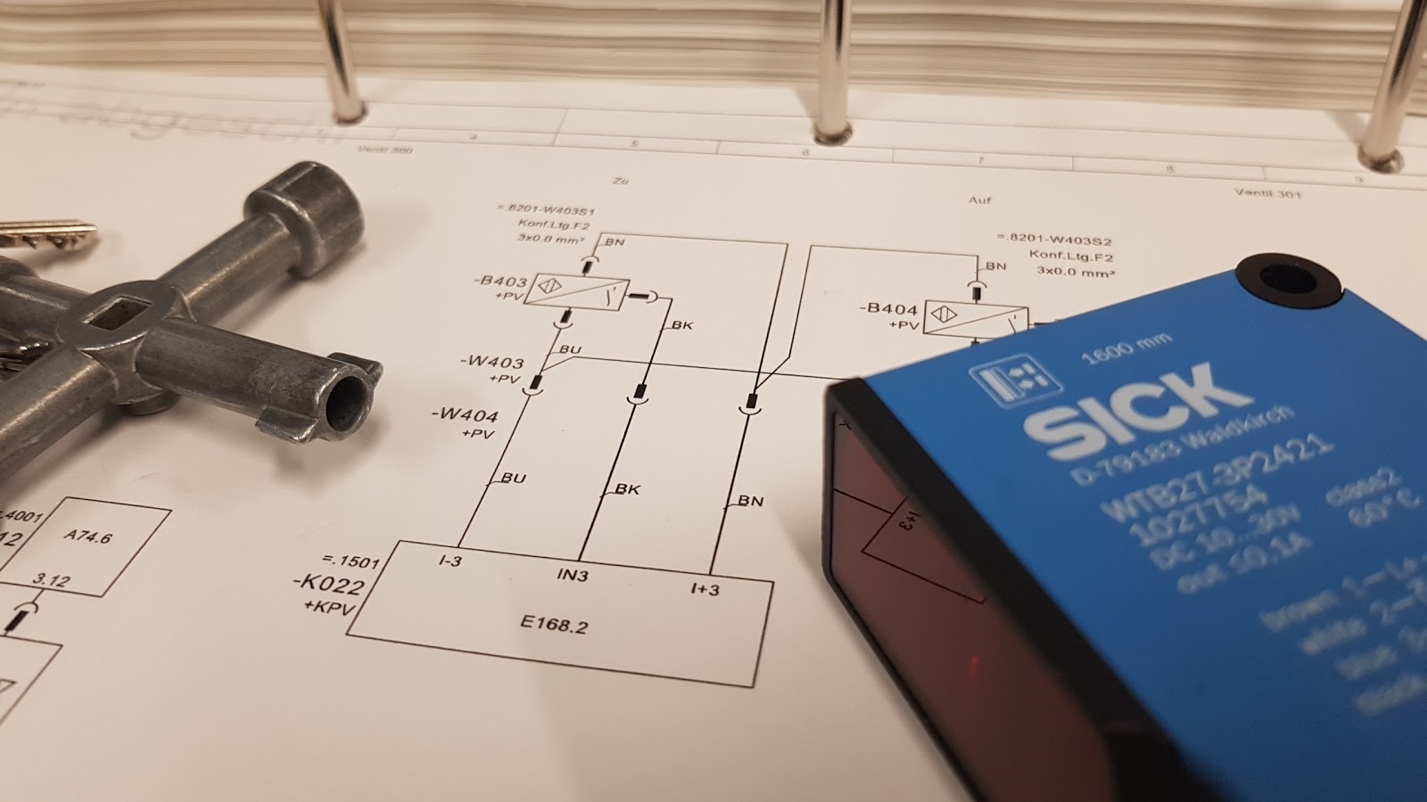
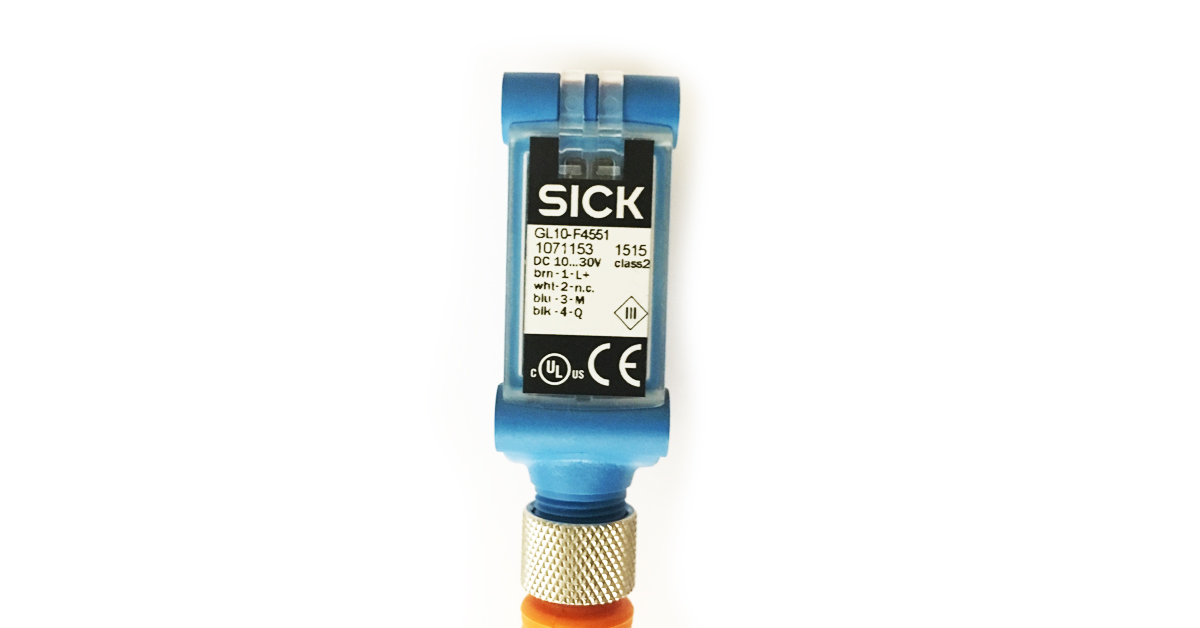
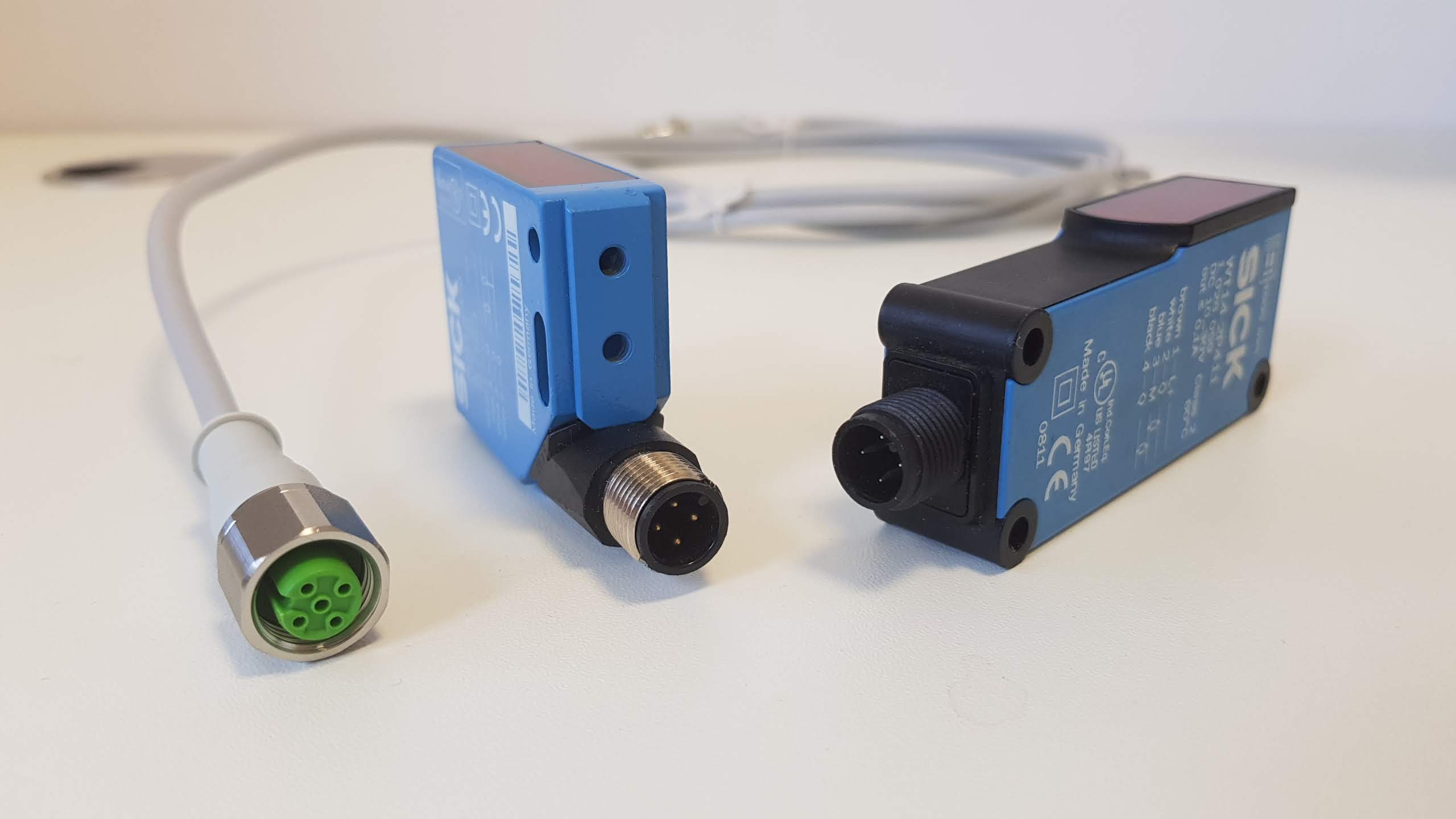
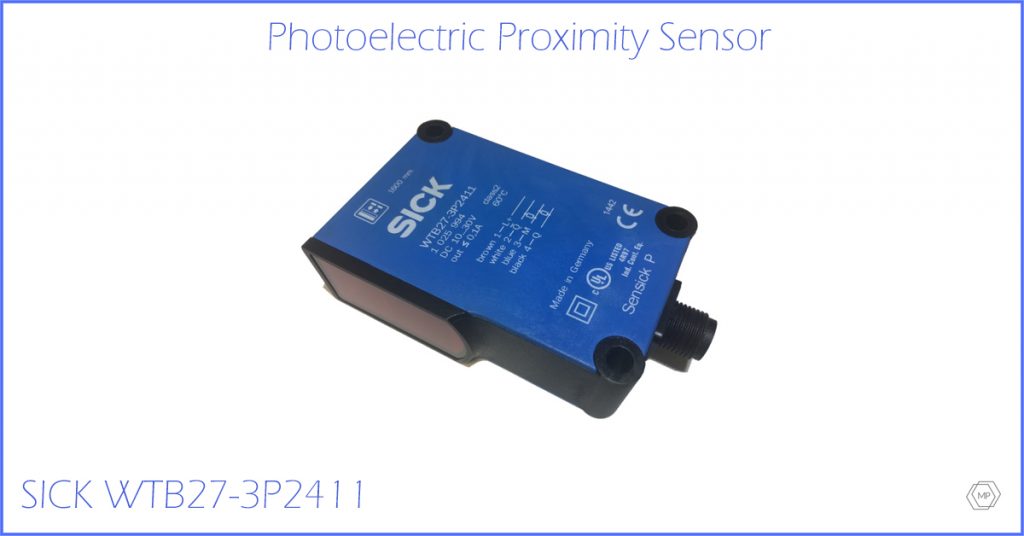
Big part of photoelectric sensors have electric schemes (connections) on their bodies. However, on the picture below you can see typical socket and pin configuration on photoelectric sensor (SICK WTB27-3P2411). If you look at very carefully, you will see small numbers from 1 to 4 on pins.

- Brown = L+
- White = /Q
- Blue = M
- Black = Q
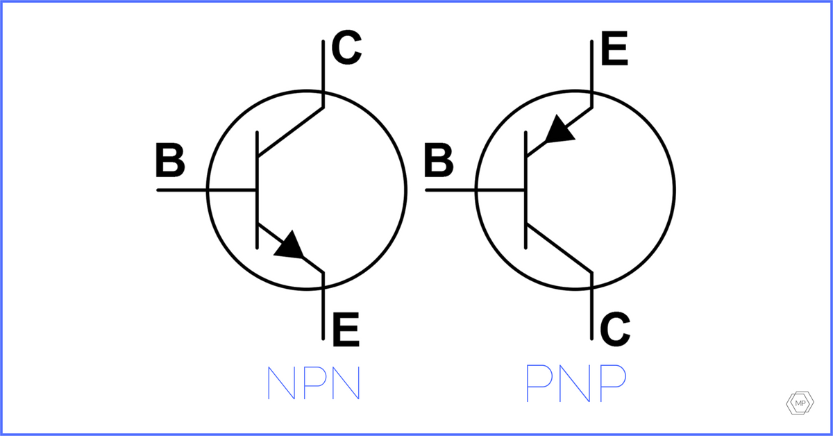
Switching of NPN and PNP output
Switching the sensor output according on NPN technology:
Photoelectric sensors with NPN transistor polarization contain in their structure NPN transistors, i.e. the low (-) potential is connected to the emitter (E) of the NPN transistor. When the sensor detects an object and the transistor is in operation, the low (-) potential will be “emitted” to the collector (C) of the transistor, i.e. on the sensor output.
Switching the sensor output according to PNP technology:
The PNP type photoelectric sensors contain PNP transistors in their structure, i.e. the positive (+) potential is connected to the emitter (E) of the PNP transistor. When the sensor detects an object and the transistor is in operation, the positive (+) potential will be “emitted” to the collector (C) of the transistor, i.e. the sensor output.
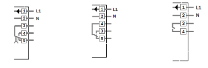
The selection of PNP or NPN sensor depends on the type of circuit in which the device is going to be used. When it’s used in a traditional control circuit – a relay type, you can normally use a PNP or NPN sensor, as it’s shown in the following images:
Important: in this case, it is recommended that the relay should be provided with a semiconductor control input. In critical cases, when it is recommended to remove the failure with this “what we have on our hands” we can use a small standard relay. Relays for higher currents should be eliminated. The coil from the clamp of the larger photoelectric sensor can create an electromotive force – a reverse current will flow, which will damage the transistor output of the photoelectric sensor.
When we choose photoelectric sensor which will be used with the PLC controller, it is important that it has to match to the type of PLC digital input card (SINK or SOURCE logic), which will be used. We have to identify the type of the sensor, which has to be used with the PLC card, on the basis of PLC manufacturer’s documentation or electrical schemes. Below you can see the typical connection of the sensor to the PLC digital input card (NPN sensor is connected to the input card in SOURCE type configuration, and the PNP sensor is connected to the input card in SINK type configuration).
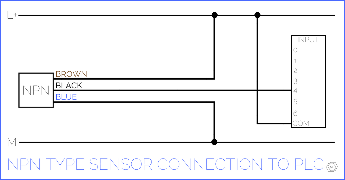
On the photoelectric sensor NPN output, the low (-) potential is emitted, so COM of input card has to be connected to the high (+) potential.
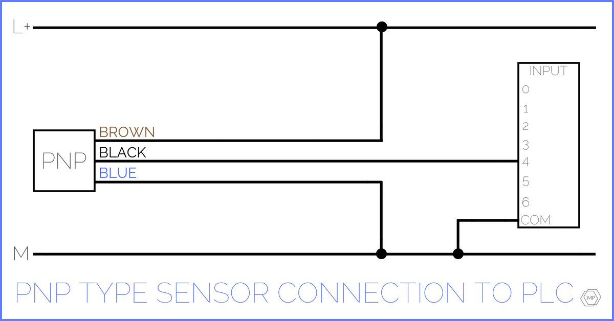
On the photoelectric sensor PNP output, the high (+) potential is emitted, so COM of input card has to be connected to the low (-) potential.
We also have various connections combination of the outputs with photoelectric sensors:
Visible light spectrum in photoelectric sensors
Depending on the application and construction of photoelectric sensors, transmitters of different wavelengths are used.
These are:
- Red spectrum – the most common one. Optic spot is usually a little irregular. It is clearly visible in a close range. With the increasing of the range, it enlarge and blur – it becomes almost invisible in brightly lit room. It is usually used in photoelectric sensors for standard applications and at the reasonable price.
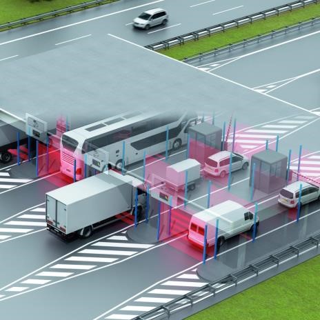
- Infrared – photoelectric sensors in infrared are characterized by wider range. They are also more resistant for small dusting and (with the support of proper electronic system) more resistant for light reflex. The disadvantage of infrared is difficulty with targeting on small objects, when we look at them from bigger distance. Special cards are helpful for finding the localization of light spot. Their surface is shining under the influence of infrared. Photo cameras in smartphones/cell phones are also helpful. Invisible light spot can be also the advantage. In the case of using the photoelectric sensors in infrared in applications such as pass gates or airport conveyor belts, no one will be complaining about glaring light. Infrared is absorbed by liquids and some of materials. This can be used for creating, from such a photoelectric sensor, a level sensor. Photoelectric sensors, based on the infrared spectrum, have usually wider range than typical photoelectric sensors in red spectrum.
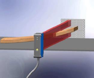
- Laser – it’s a coherent and focused beam of photons. Lasers are characterized by small light spot (from a certain distance). They are used for precise detection of small objects, detection of object location, right after seeing its edge, positioning some object. In connection with proper technology, photoelectric laser sensors can detect the presence of flat object on another flat object, defect objects under a steep slope, detect small holes, etc. Lasers are divided into classes. Class 1 lasers are thought to be the safest. Right after them, are class 2 lasers. In practice, in photoelectric sensors, these two classes are the most commonly used.
- PinPoint – photoelectric sensors with bright, clearly visible, red, circle, uniform light spot. The light spot is bigger than in the case of laser spot and has a diameter of few millimeters. Photoelectric sensors with PinPoint transmitter are mostly more advanced. They also require more advanced opto-electrical layouts. They can detect small objects, small displacements. Versions for wider ranges can match to versions in infrared. In some applications they can even replace photoelectric laser sensors. Below you can see the comparison of light spots of laser, PinPoint and common LED transmitter:

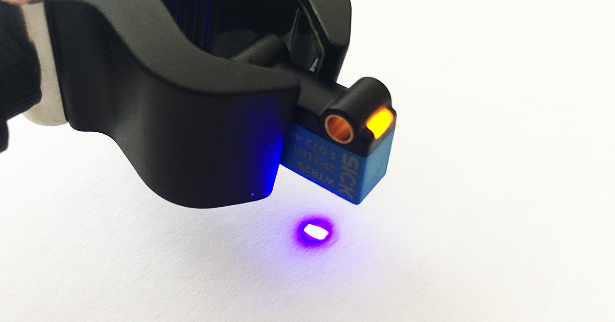
- Blue spectrum – rarely used, mostly for detecting objects with dark, shining, partly transparent surface. Blue spectrums reflects from these surfaces better than others light spectrums (more light is coming back to the photoreceiver). They are mostly used in photoelectric sensor for detecting, for example photovoltaic cells, liquid crystal displays – electronic industry. Below you can see the photoelectric sensor for detecting objects with dark, shining, semitransparent objects:
- Ultraviolet – these are usual photoelectric sensors, usually called luminescence sensors. They detect the presence of markings, which under the lightning of UV spectrum reflect the light displaced in the infrared spectrum. These marking can have the character of overprints, which are invisible to human eye (e.g. labels on packages or their elements), small lines made with chalk or marker. Some of them – especially the cheapest models, barely manage with the white, cream-colored surfaces made of e.g. paper. Such a luminescence sensor can wake-up for a surface or for a mark (luminophore). They are used in packaging; food, cosmetics, wood (e.g. for marking the wood defects) industry, ceramics industry.
- RGB – photoelectric sensors, which have few transmitters, in red, green and blue spectrum. They are usually used in color and contrast sensors. Electronics of the sensor decides by itself (in some cases the user can make a choice of light spectrum), which light spectrum (or their connection) is the best for particular application. They are used in packaging; food, cosmetics, pharmaceutical industry.
- White – used in old models of photoelectric sensors, e.g. proximity sensors, when the LED technology wasn’t available. Till nowadays they are used in some models of contrast sensors. They well detect various marker colors, if they occur one after another – the exception is for example yellow on white background.
Types of photoelectric sensors
Typical division of photoelectrical sensors:
- Photoelectric proximity sensors
- Photoelectric retro-reflective sensor
- Through-beam photoelectric sensor
- Fiber-optic sensors
- Rangefinders and micro displacement sensors
- Contrast sensors
- Luminescence sensors
- Color sensors
- Light curtains (photoelectric beams)
- Specialized photoelectric sensors
- Photoelectric sensors with I/O Link and Smart Sensors
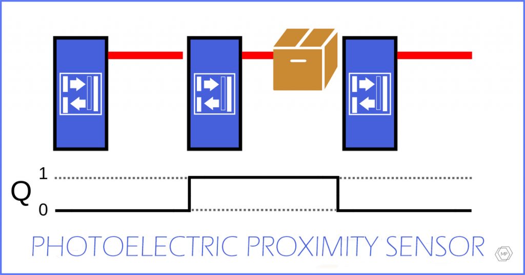
Photoelectric proximity sensor
This is the type of photoelectric sensor where transmitter and receiver are in the same housing. Transmitter and receiver optics are set at an angle to each other. Receiver observes particular are4a – this is the range of photoelectrical sensor. Photoelectric proximity sensors are usually implemented as 2-lens layout. The most common solution is setting the transmitter at the top, and receiver at the bottom part.
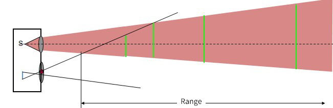
Photoelectric proximity sensors detect the object immediately after receiving reflected light from the object’s surface. If no object will be placed in from of the photoelectric sensor, the light will not be reflected back from the surface of the object to receiver. When the object is present, the output changes its state from low to high (for the Light ON function).
There are two versions of photoelectric proximity sensors, e.g. energetic proximity sensor, proximity sensors with background suppression, proximity sensors with background removal, optical proximity sensors, proximity sensors with foreground suppression, proximity sensors with one or more transmitters, etc. these solutions will be discussed in the next article.
The main advantage of photoelectric proximity sensors is the possibility of detecting objects by looking at their surface without using additional elements. Disadvantages depend on types of technologies used in construction of photoelectric sensors.
Photoelectric retro-reflective sensor
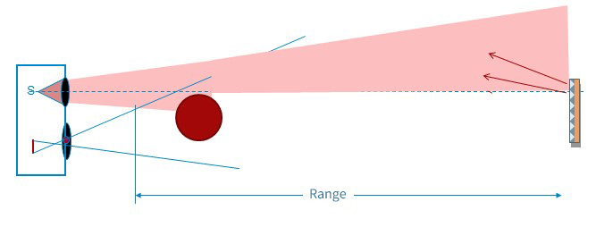
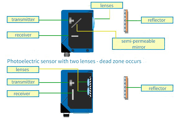
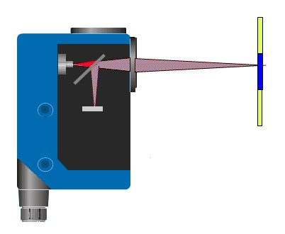
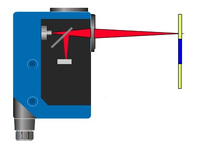
Photoelectric retro-reflective sensors also have transmitter and receiver in the same housing. Transmitter “shines” to so-called reflector. If the transmitter is properly pointed on the reflector, the light after going out from the transmitter, goes through the lens, then polarizing filter, it reflects from the reflector and get (in some part, because part of light succumbs to dispersion) back to the photoelectric sensor. After reflecting from the reflector, the light beam goes through the polarizing filter with different polarization. If the light with proper polarization will be passed through the lens and further to the receiver, then the electronics knows that photoelectric sensor “sees” the reflector. If something will cover the reflector, the polarizing filter will not pass the differently polarized light, electronics of the photoelectric sensor reacts by the change of logic state on the output.

Photoelectric retro-reflective sensors are usually made in single or dual lens (autocollimation). The advantage of autocollimation is that the light is send and send back through the same lens. Thank to it, there is no dead zone, i.e. the photoelectric sensor can detect objects right in front of its front glass.
Signalization through the LED diodes, on the photoelectric retro-reflective sensors bodies, operates with the Light ON function, because in normal operating conditions they see the reflector, which reflects the light beam back to the sensor receiver. If no objects blocks the light beam in the receiver, the output is active. If the object is located between the photoelectric sensor and the reflector, the light beam cannot get to the photo receiver, causing switching of the output on a low state. In practice, some of the users choose the Dark ON output signalizing the disruption of the light beam (i.e. detecting of the object).
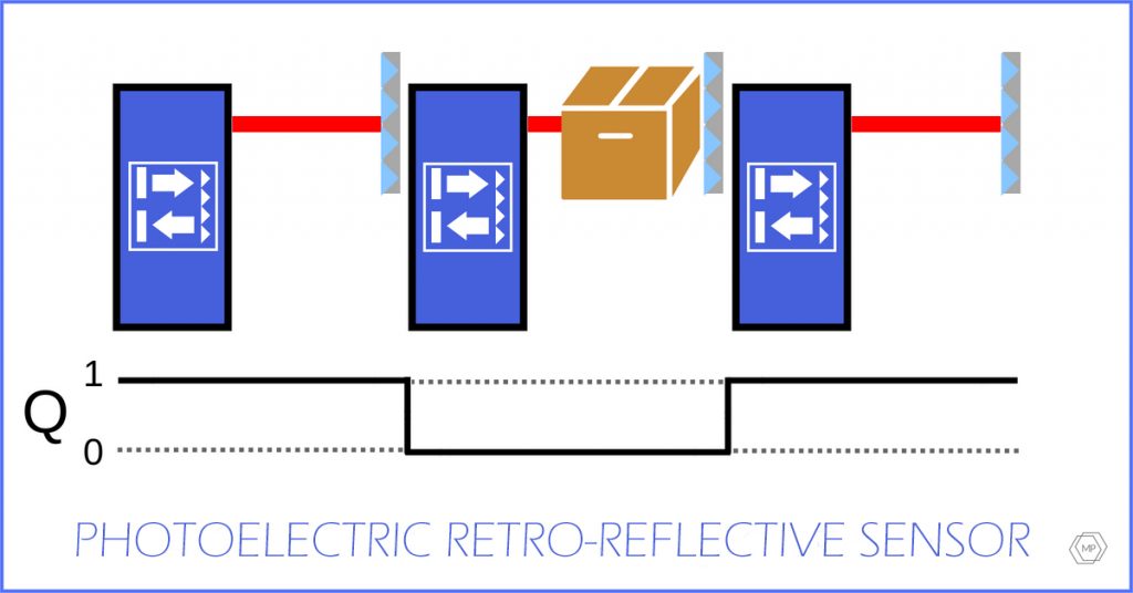
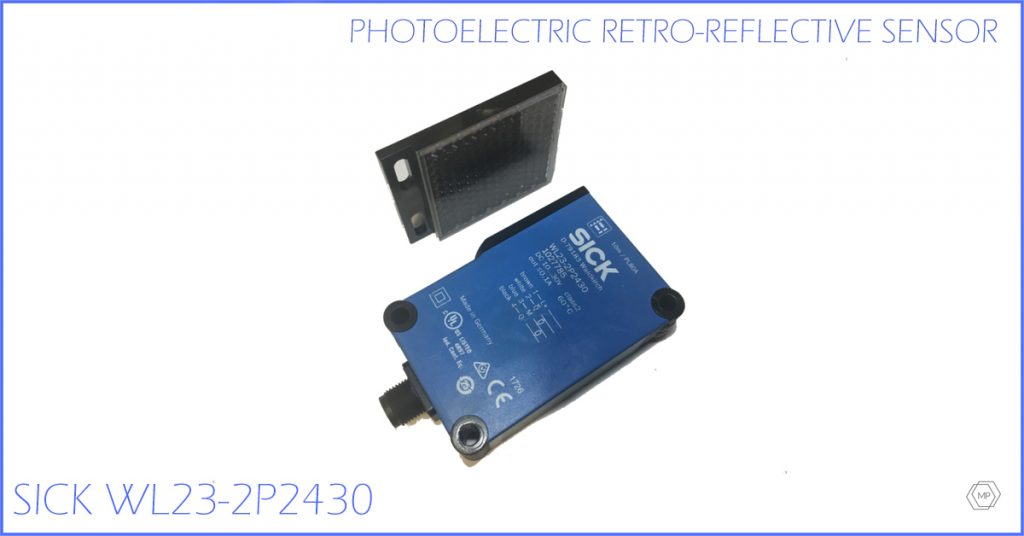
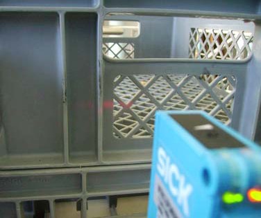
Photoelectric retro-reflective sensors are widely used because of its economic price and easy installation. W-23-2 type became one of the most often used photoelectric sensors, especially in storage systems for pallets detecting or for detecting containers on conveyors.
Photoelectric retro-reflective sensor 
Photoelectric retro-reflective sensor 
Photoelectric retro-reflective sensor 
Photoelectric retro-reflective sensor
Another advantage of photoelectric retro-reflective sensor is the range, which is much bigger than in photoelectric proximity sensors. Polarizing filters and reflectors cause that it’s hard to optically interrupt these photoelectric sensors. It’s easy for them to operate next to strongly shining objects, e.g. roller conveyors or devices made of polish stainless steel. Some of the versions are able to detect objects which strongly depolarize the light, e.g. some package or pallets which are wrapped in stretch foil. The disadvantage of photoelectric retro-reflective sensors is the need of using reflectors/fastening on the device or line – very often dedicated to specific range or specific type of photoelectric sensor. Sometimes, because of too small housing, reflective foils are used. Usually they have worse light parameters (but there are exceptions).
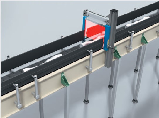
Photoelectric retro-reflective sensors have laser version, for detecting of transparent objects (various classes of material transparency), versions without polarizing filters (rarely used), versions with linear light spots used as small gates, etc.
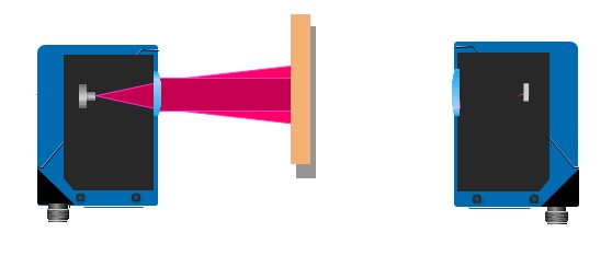
Through-beam photoelectric sensors
In these photoelectric sensors, transmitter and receiver are placed in separate bodies.
The transmitter has LED or laser diode, and the receiver detects light through the opto-electronic layout. Thank to this construction and use of laser diodes, PinPoint or infrared, through-beam photoelectric sensors are characterized by very wide ranges. They usually operate as Dark ON, because in normal operating conditions the transmitter lights up the receiver. Dark ON means the active output of the photoelectric sensor in the case of beam interruption (covering the receiver).
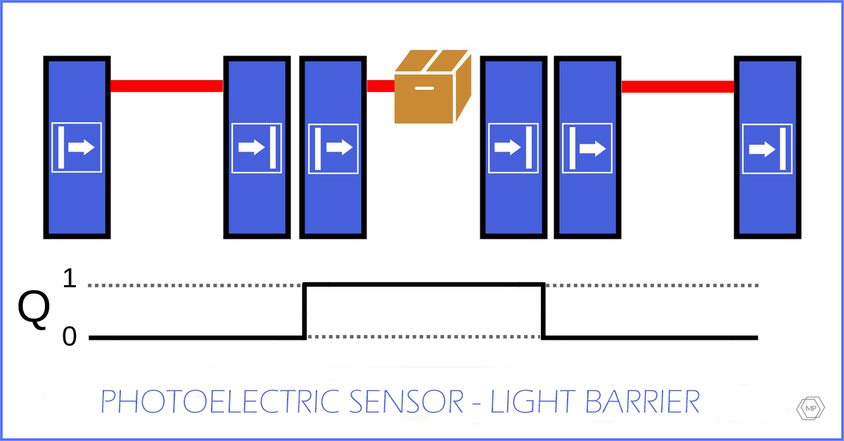
Characteristic of Q output of sensor – light barrier type.

The advantages of through-beam photoelectric sensors include a wide range. When they are made in proper spectrum, e.g. in infrared, they can operate in increased dustiness – infrared is more shrill than typical light spectrums, and in the case of through-beam photoelectric sensors the light beam goes only once through the distance between transmitter and receiver.
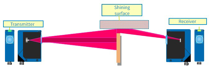
The disadvantage is the necessity of mounting two bodies (it’s not always possible) and increased risk of optic interruption through the shining surfaces, which are located in the side, or difficulties in detecting of transparent objects.
Properly selected laser through-beam photoelectrical sensors are a good solution for precise positioning of objects. Through-beam photoelectric sensors are also made with laser optic, where the light spot is linear.

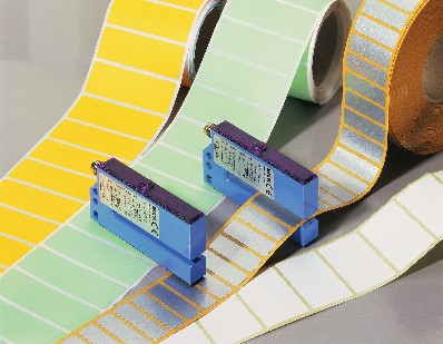
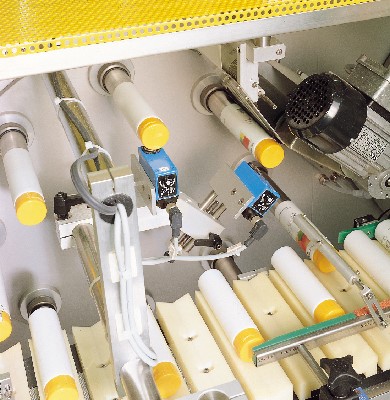
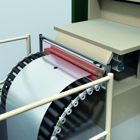
The specific type of through-beam photoelectric sensors is so-called photoelectric fork sensor. Transmitter and receiver are located in the same body, which has a specific shape. These photoelectric sensors are used as a detecting gates, e.g. of caps on the bottles; or for detecting the labels on carrier foils.

Fiber-optic sensors
This photoelectric sensors are also called fiber optic amplifiers. In this type of sensors, the optical fibers (their light conducting elements are made of material, which resembling some of the characteristics of glass).
Optical fibers – according to the version – are very flexible and they provide the possibility of use in applications with small housing. Thanks to their low weight, they can be used in gripper elements. Properly selected optical fibers are used in some explosion danger areas, because the optical fiber conducts only the light, and the sensor element can be placed beyond the area. Some of the optical fiber versions are very resistant to chemical substances, high temperature. They are used for detecting transparent objects, levels (also liquids) or during use of the converging lenses for detecting the small objects. The most important matter here is selecting the proper sensor and optical fiber for specific operation. For example, the photoelectrical sensor operating in infrared spectrum will not be properly operating with the optical fiber, which conducting light part will be made completely of material.


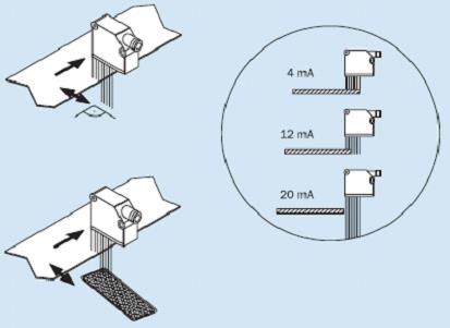
Rangefinders and micro displacement sensors
These sensors are used for detecting of objects or distance measurements – in the case of rangefinders of category of single meters or kilometers.
In the case of micro displacement sensors, we are talking about small distances (or material thickness) from the category of single mm or cm, but with accuracy on the level of micrometers.
In the case of rangefinders and micro displacement sensors, there is used a version with switching outputs, analog outputs, or the communication after the protocols, e.g. Profibus, CanOpen. SSI , RS 485.
Contrast sensors
These sensors are used for detecting so-called markers.
Contrast sensors, depending on the type of used technology and size, are made as 2 lens or with autocollimation (single lens).
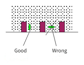
The key activity here is selecting the distance between the contrast sensor optics and material, on which the marker in placed (sensors have constant focal length – the range cannot be regulated, e.g. by the potentiometer), selecting the sensor with proper light spectrum (RGB or white light), watching the tightness of material for providing the appropriate distance, size and spot position towards marker. The light spot has to fit on the market and “don’t cross” the overprint area.
Contrast sensors are used for controlling the overprints, foil or paper cutting, board curving in machines called board machines, cutting the labels, tube positioning or controlling of the material on the roll. The contrast sensors are programmed by pointing the marker and then the background (static method) or sliding the material with bigger amount of markers. The sensor is learning how the marker and background look like (dynamic method). Sometimes, after learning, there is a need for turning back the logic (Light ON or Dark ON). Most of the sensors have two outputs with opposite logic states (so-called complementary outputs) or the possibility of changing the output function.


One on the most important parameter in contrast sensors is their switching frequency. In most applications, during fast sliding of material and big amount of markers on a short section of tape/cardboard, the very fast reaction time is needed. Typical switching frequencies in contrast sensors are from 10 kHz in simple, cheap sensors for basic operations, up to 70 kHz in versions dedicated for quick and precise markers detecting.
Besides many advantages, the contrast sensors have also few disadvantages.
We always have to point the marker and the background. They have to differ from each other in a clear way. The better class and optical parameters of the sensor, the smaller difference between marker and background the sensor is able to recognize (e.g. the dark navy marker on the blue background is more difficult to detect). Markers have to have a uniform overprint. When the markers are printed in a wrong way or they have discolorations, then the contrast sensor will have to wake up e.g. two times, not once.
Another critical case is detecting markers (especially the black ones) on transparent foils. The reflector, piece of light tinware or different light material should be placed at the exact height of light spot on the markers line under the foil.
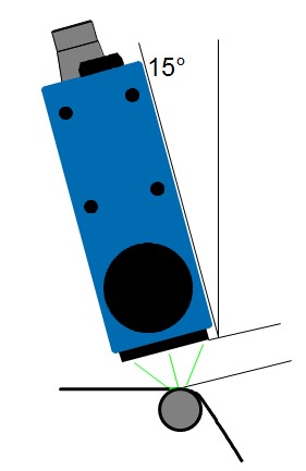
Simple contrast sensors cannot deal with shining surfaces. This situation does not occur in the case of advanced sensors. In critical situations, 15 degrees inclination of the sensor will help.
Luminescence sensor
These sensors detect the presence of markers, which under the influence of UV spectrum reflect the light displaced in red spectrum. These markers can occur as overprints invisible for human eye (e.g. labels on packages or their parts), small lines made with the special chalk or marker. Some of them – especially cheaper models, cannot deal with light or cream-colored surfaces based on paper or material. Such a luminescence sensor can wake up to the surface and the marker (which contains so-called luminophore). This problem is minimalized in more advanced models with the sensitiveness regulation. We have to be careful because most of the models – also the cheaper with simpler construction, also have the sensitiveness regulation which is not able to minimalize the interruptions. These sensors are used in cosmetic and food industry, in pharmaceutical industry (for controlling the presence of leaflets in the packages) or in wood industry (e.g. for marking the wood defects).


Color sensors
They are used in the case of small color difference between the marker and the background, detecting objects in particular color or object segregation by its color, if the color sensor has several memory banks and outputs supporting them.
Color sensor in contrast to contrast sensors require during programming the indication of color, which interests us. They are not interested in the background color, under the condition that it’s different from the object color. High class sensors have the color tolerance. With the small color tolerance, such a sensor can differentiate the colors so little different from each other, that it is difficult to distinguish them for the average user with the naked eye.
Color sensors are more expensive than contrast sensors. Their disadvantage, in contrast to contrast sensors, is lower switching frequency. It’s usually decreasing when the tolerance of programmed color is reduced and when more than one memory bank is used (if the color sensor has several memory banks).
Color sensors are usually made with the RGB transmitters.
Light curtains (photoelectric beams)
In this group there are several sub-divisions. Here you can see exemplary types of light curtains:
- multibeam light curtain, in which crossing the beam causes activating the output,
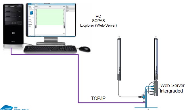
- versions with possibility of programming different sequences from level of the PC/laptop with ready programs,
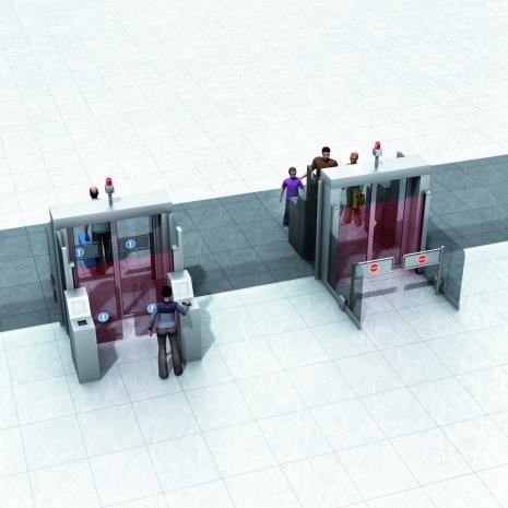
- versions for logistic applications, downloading systems, controlling the presence of objects falling out from ejector machine,
- versions with switching and analog outputs for measurements of high or overload, e.g. pallets,
- versions operating in different types of network basing on Ethernet, RS 485, etc.


Specialized photoelectric sensors
(Designed to perform specific tasks)
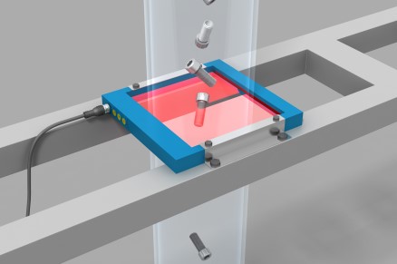
These photoelectric sensors, on the stage of designing, are intended for specific tasks. These can be e.g. photoelectric sensors with linear spots, working as small gates controlling edge guidance (e.g. transparent foils), detecting transparent objects (without using the reflector), counting packages, etc.
Photoelectric sensors with I/O Link and Smart Sensors
I/O Link opens new possibilities of communication between installation control system and devices. Sensors and actuators becomes more active members of process in automation network. As transmitters they transmit the information about errors and statuses to the control system. As receivers they receive signals and process them. It allows to optimize the costs and processes at all stages of creating contents for all industries.
IO-Link involves a point-to-point connection that may be located underneath any given network for communicative integration of the lower field level.
Because of the communication after IO-Link the photoelectric sensors besides sending signals and information about the phenomena, offer expanded functions of diagnostics, parametrization, quick displacement of machines and lines e.g. according to implemented patterns (recipes), etc.
Smart Sensors (intelligent sensors) are more advanced version of sensors operating after IO-Link protocol.
They include more advanced functions, which are realizing specific tasks. Some of the functions are very similar to functions realized in PLC controllers, for example timer, debouncer, counter, virtual outputs, basic logical functions, etc.
In some cases, properly selected and programmed photoelectric sensors – Smart Sensor type, are able to realize the whole task without using the PLC controller. In other cases Smart Sensors offload the PLC and increase the efficiency of machines or production lines.
Summary
As you notices at the beginning, this is the first part of the articles about photoelectric sensors. I hope that you like this article and you will use some of these contents in your adventure with automation.